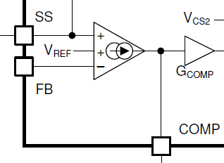
I feel the datasheet is unclear in situations where the FB pin is grounded, such as in isolated flyback designs. Some application notes claim the error amplifier is disabled when FB is tied to ground.
In my design (isolated flyback), I had a pullup on the COMP pin to 6.85V, along with an optocoupler. The regulator worked fine even when I removed the pullup resistor, which means the COMP pin is actually sourcing current to the optocoupler. I can not find any information in the datasheet regarding the source of this current, is it coming from the error amplifier or is the current coming from another source within the regulator?
Best regards
Alexander