This thread has been locked.

If you have a related question, please click the "Ask a related question" button in the top right corner. The newly created question will be automatically linked to this question.

TPS61165: High Current in CTRL Pin : issue during PWM dimming

Part Number: TPS61165

Hi,

After reading different posts from this forum relating to some PWM managment issues with the CTRL pin when the voltage on the CTRL pin is set to 3.3, 5V, managed by an Arduino or not , I encountered the same kind of error.

Following the type of the interface (value of the pull-up, value of the reference voltage of the pull-up, direct management by a logic gate) the PWM works fine or not. The timings of the PWM don't change between the tests  [and the 160µs low state is always respected without any glitches below 50 ns).

Although I notice that the current flowing into this CTRL pin is quit high (7 mA for a +5V logic gate with  a Vin at 12v) and if I don't have a certain amount of current (let say 2/3 mA) I encounter some issue (no backlight on or a PWM management). 

Do we need a specific amount of current into this PIN during the PWM mode (without easyscan)? Is it normal to have around 7 mA flowing into this pin ?

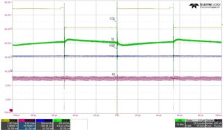
Picture attached is the current into the CTRL pin from my logic gate (only the timing and Ipp are relevant) 

  • hi alexandre

    Actually I am not sure I fully get the point on what the issue is. Do you mean that TPS61165 does not work normally with 3.3V or 5V PWM input? and you are suspecting the current into ctrl pin? 

    Would you mind sharing more information how this device behaviors in abnormal state?  Does the LED current follow duty cycle change or nor?

    It would be helpful if you provide waveforms of SW pin, FB pin, comp pin in this condition.  

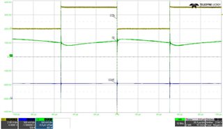
  • Please find hereunder some waveforms :

  • hi alexandre

    I would like to confirm the operation condition with you and pls help add unknow condition: Vin=12V, LED string voltage Vled?, LED string current Iled?   input PWM frequency 8kHz, Rset? Pls also attach schematic if available.

    Besides, from the waveforms, 50% duty cycle PWM has been applied on the device and FB is regulated at ~100mV average which seems to consistent with the calculated value 200mV*50%. However, from the result of SW, its voltage near input voltage which means it does not switching.  

    Currently, I will check schematic parameters under your operation condition first. BTW, have you tried to replace a new TPS61165 or its a common phenomenon?