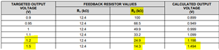
Hi team,
When I changed Cff from 10nF to 100nF, the load regulation got worse.
Is there a relationship between Cff and Load Regulation?
Best Regards,
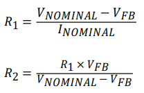
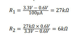
Hi team,
When I changed Cff from 10nF to 100nF, the load regulation got worse.
Is there a relationship between Cff and Load Regulation?
Best Regards,