A related question is a question created from another question. When the related question is created, it will be automatically linked to the original question.
If you have a related question, please click the "Ask a related question" button in the top right corner. The newly created question will be automatically linked to this question.
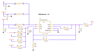
In order that they are posted here are my comments on each schematic
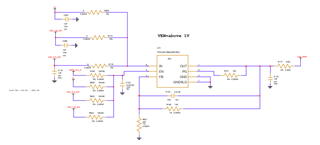
U13
Move one of the Cin caps to the other side of the 0 Ohm resistors, this will reduce the parasitic ESR/ESL of the resistor and provide the lowest impedance to the input node.
This could also allow you to eliminate 2 of the 3 caps currently shown since you would need one before each 0 Ohm, all paths would be taken care of by the single cap next to the IN pin.
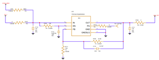
U10
you may want to adjust the FB resistors, currently they are set such that there will be a 2.3% error from the nominal voltage shown on the schematic
I could not verify the PG pull up resistor value (R333) we generally recommend that they be 10k-100k Ohms.
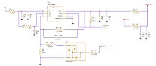
U106
The two intended output voltages are not listed on this schematic so you will need to verify that these are correct.
When the FET is off I calculate0.675V and when the FET is on I calculate 0.948V
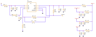
See my comments below, some are similar to my last set.
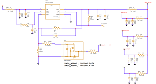
U12
Move one of the Cin caps to the other side of the 0 Ohm resistors, this will reduce the parasitic ESR/ESL of the resistor and provide the lowest impedance to the input node.
This could also allow you to eliminate 2 of the 3 caps currently shown since you would need one before each 0 Ohm, all paths would be taken care of by the single cap next to the IN pin.
You may want to adjust the FB resistors, currently they are set such that there will be a 4.5% error from the nominal voltage shown on the schematic