This thread has been locked.

If you have a related question, please click the "Ask a related question" button in the top right corner. The newly created question will be automatically linked to this question.

LP3965: About LP3965-ADJ

Part Number: LP3965

Hi, support team

My customer has the questions as follow:

1. About LP3965-ADJ, datasheet said that:
    "To obtain a desired output voltage, can be used with R1 always a 10kΩ resistor."

    Could you tell me the detailed reason of "R1 always a 10kΩ resistor"? (Detailed reason about why must R1 use 10kΩ resistor)

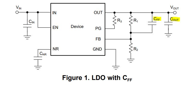
2. Cf and Cout are used for output stability.

    Could you tell me their respective uses and why they are connected in different places?

3. And why Cf must be between 68pF ~ 100pF?

Thanks so much.

Best regards,
Yuki

  • Hey Yuki, 

    1) The 10kΩ resistor is used for help with stability of the LDO. 

    2) The Cf is referring to a Cff or a feedforward capacitor instead of a Cout capacitor. They are connected in the network differently as seen below. 

    Pros and Cons of Using a Feedforward Capacitor with a Low-Dropout Regulator (ti.com) please see app note on Cff to best help explain the purposes and differences. 

    3) The Cf is used for stability. For this part adding it will improve the phase margin due to the zeros and poles placement. 

    Thanks, 

    McKyla

  • Hi McKyla,

    Thanks so much for your kindly support.
    And sorry for my late reply.

    About CFF, my customer has a more question:

    In the following Application Report,
    www.ti.com/.../snva167a.pdf
    "The poles in the loop of the LDO can cause oscillations if not compensated for by other zeroes, which will add some phase lead. One of the traditional methods for doing that is to add a feedforward capacitor across resistor R1, which forms a pole-zero pair."
    If there's no CFF, it may cause oscillations.

    My customer need to know the conditions prone to oscillation.

    My customer thought the following three situations prone to cause oscillations:
    1. When the load is less than 10mA, very low load
    2. When the load is more than 1A, very high load
    3. When the load suddenly fluctuates (example suddenly from 100mA to 1A, or 1A to 100mA)
    Are the above three situations right?
    Please tell me are there other conditions that prone to oscillations.


    Thanks so much.

    Best regards,
    Yuki

  • Hey Yuki, 

    If the Cff is used these cases should not cause oscillation. If there is not a Cff, the most likely places where oscillation may occur is at very light loads under 1mA and then they are going from from no load or very light loads (1mA) to full load. 

    Hope this helps! Apologies for the delayed response. 

    Best, 

    McKyla

  • Hi McKyla,

    Thanks so much again for kindly professional support.
    And sorry for my late reply.

    About the above question, my customer has one followup question:

    Oscillation may occur when load going from less than 1mA to 1.5A,
    so how much current variation speed will cause oscillation?

    (The customer need to know: current variation speed above ?????mA/s will cause oscillation when load going from less than 1mA to 1.5A)

    Thanks so much.

    Best regards,
    Yuki

  • Hey Yuki, 

    No problem. 

    Oscillations may occur if the Cff is not used AND at no load or very light loads (1mA) or starting up (during very light loads). 

    Hopefully this helps!

    Thanks,

    McKyla

  • Hi McKyla,

    Thanks so much for your reply.

    So sorry I may not make it clear.
    The customer know "Oscillations may occur if the Cff is not used AND at no load or very light loads (1mA) or starting up (during very light loads). "

    And the customer ask that : How much current variation speed will cause oscillation when Cff is not used AND load going from less than 1mA to 1.5A.
    (For example, current variation speed above ?????mA/s will cause oscillation when Cff is not used AND load going from less than 1mA to 1.5A.)

    Thanks so much.

    Best regards,
    Yuki

  • Hey Yuki, 

    This is not something that has been tested or known as it is outside of recommended operating conditions. We strongly recommend using a CF between 68pF and 100pF for output stability as stated in the datasheet. Additionally, if this is not used the specs in the datasheet may not hold true as the design would not follow the datasheet recommendations. Also please note: The lowest value of input capacitance that can be used for stable full-load operation is 68 µF (assuming it is a ceramic or low-ESR Tantalum with ESR less than 100 mΩ). 

    Hope this helps! 

    Thanks,

    McKyla