This thread has been locked.

If you have a related question, please click the "Ask a related question" button in the top right corner. The newly created question will be automatically linked to this question.

UCC27282: Schematic review

Part Number: UCC27282

Hi Ti team,

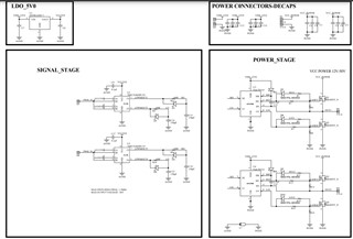
I am developing a 1Mhz 50V output Full Bridge for My transducer.

Please review the schematics given.

Does UCC27282 can switch 1Mhz?

  • Hello,

    Thanks for contacting us. With regards to your schematic here are our recommendations. At the input pins, we recommend adding RC filters for high frequency noise. Small filter such as 10-Ω resistor and 47-pF capacitor might be sufficient to filter noise at the inputs of the gate driver device. If not desired, we recommend adding place holders in schematics.

    We recommend adding 2 local bypass capacitors across VDD and GND. One low value capacitor for high frequency filtering placed very close to VDD and GND pin (typical value of 100 nF), and another high value capacitor for device bias requirements (typical value is great or equal to 10 times your bootstrap capacitor value).

    In a similar manner, two capacitors across the HB to HS are recommended. One low value small size capacitor for high frequency filtering and another one high capacitance value capacitor to deliver HO pulses (Cboot). The value of Cboot depends on the gate charge of your high-side MOSFET. To make sure you have the correct value, you may refer to the bootstrap calculator in Half Bridge Calculator.xlsx. For the bootstrap circuit, the UCC27282 has an integrated 100V bootstrap diode. If an external bootstrap diode is needed for your application, it is recommended to choose a Schottky diode, or one with fast recovery, which has a low forward voltage and can handle Vbus and transients.

    Regarding your question, we do not generally specify switching frequencies our parts can handle. The main care-about from the driver’s point of view, is making sure the part does not exceed its recommended maximum junction temperate which for the UCC27282 is 140°. To determine if operating at 1MHz will not cause the driver to overheat, you need to calculate the power losses resulting from your design. These calculations can be done by following the steps in Section 8.2.2.2 of the UCC27282 datasheet or simply using the Power Dissipation calculator in Half Bridge Calculator.xlsx.


    Regards,

    Hagar

  • You are welcome! Let me know if you have any further questions, otherwise, please click the Green button below.
    Thanks