This thread has been locked.

If you have a related question, please click the "Ask a related question" button in the top right corner. The newly created question will be automatically linked to this question.

LP2989: ERROR Pin anomaly?

Genius 17695 points
Part Number: LP2989

Hi Experts,

Good day.

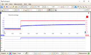
While debugging a shut-down and re-boot issue, I observe that the /ERROR pin on the LP2989 reports a "Good" signal during boot-up well before the power supply has reached the target value.  Is this a known issue?  Is there something I should do to correct this?

In the images, D0 is the /ERROR signal.

Thank you.

Regards,
Archie A.

Image_1

Image_2

Image_3

  • Hey Archie,

    How do Vin and Vout look in comparison to /ERROR? Is it possible to get a scope capture of all 3 on the same plot?

    Also what is the function of the 220 and 300 resistors?

    Thanks,

    -Jimmy

  • Hello Jimmy,

    Thanks for responding.

    Vout is shown as the upper blue trace. Vin should be a solid 5VDC from an AC-DC line converter. I can get a trace of the 5VDC if you need it, but not until next week. Are you suggesting that if the Vin rises slowly, the ERROR signal could be fooled? The load resistors are intended to drain a super-cap, which was still at 1.5VDC 30 seconds after power off. This might confuse an SDRAM.

    Thank you.

    Regards,
    Archie A.

  • Hey Archie,

    Is Vout in the first scope capture or third image above? What is being shown in the other image?

    What are D1 and D2? It would help to see Vin, Vout, and /Error on the same plot to compare what happens in the same timeframe.

    Thanks,

    -Jimmy

  • Hi Jimmy,

    Just got information from customer.

    In both images, the upper blue trace is Vout. Once is Power Up [Image_1 - see above post], and the other is Power Down [Image_3]. D0 is /Error. D1 and D2 are indicators of internal activity. In the Power Down image, D1 shows the SaveData() routine. I will need to reset my system to show both Vin and Vout.

    Here is the new scope trace. The red trace is the 5V Vin being fed to the regulator. The blue trace is the 3.3V Vout, rising slowly as it charges a super-cap. D0 is the /Error signal, which shows "Good" immediately. That should not happen until the Vout reached ~3.1V.

    Thank you.

    Regards,
    Archie A.

  • Hey Archie,

    Does the /Error pin sequence correctly when the supercap is disconnected?

    Thanks,

    -JImmy 

  • Hi Jimmy,

    Here are the scope traces during power-up without the super-cap on the 3.3v side. It shows /Error is incorrect immediately. Note 10ms/div time scale, much faster than the earlier traces.

    Is this enough?

    Thank you for your guidance.

    Regards,
    Archie A.

  • Hey Archie,

    Is it possible to increase the ramp rate of Vin and to zoom in on the first 10ms around startup so we can see when exactly /Error goes high?

    Thanks,

    -Jimmy

  • Hi Jimmy,

    Thanks  for your responses.

    I can't adjust Vin in the circuit. At this point, I have provided enough data that your engineers should be able to reproduce the situation. We accept that this behavior is real, and we will find a way to work around it.

    If you are aware of a similar device that behaves properly, let me know and we will consider switching to it.

    Thank you.

    Regards,
    Archie A.

  • Hey Archie, 

    It is difficult to see the timing relation between Vin, Vout, and D0(/Error). 

    We would be interested in trying to recreate this to examine the timing. Is there anything connected to the PWRGOOD signal? What are the logic levels for the digital signal D0?

    Thanks,

    -Jimmy

  • Hi Jimmy,

    Thanks for your prompt responses.

    The PWRGOOD signal is tied to the Vout with a 100K resistor, and also to a digital input pin on the MSP430 processor (Port5.0).

    Regarding the timing, it doesn't matter. The signal reports that the 3.3V is good, when Vout is less than 3.0V. When and how doesn't matter. This signal should remain LO until the Vout is within 5% of the specified value. This works properly when Vin is removed and Vout falls below 3.1V, as shown in the attachments.
    At this point, it is an academic exercise.

    The device doesn't work as intended to indicate when power-up is stable, and we will work around it.

    Regards,
    Archie A.