Other Parts Discussed in Thread: BQ24650
Hi,
We just bought a BQ24650EVM-639 demo board that is configured as a charger with a maximum current of 2A.
Since we have to design a 4A charger, and we want as real a test as possible, we plan to make the following changes to the board.
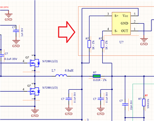
L1 - Inductor, SMT, 102mΩ, 3.0A / 7.0A, 20% - IHLP2525CZER100M01
Change to: L1 - Inductor, SMT, 54mΩ, 4.5A / 8.0A, 20% - IHLP2525CZER6R8M01
R6 - Resistor, Metal Film, 20mΩ 1/4 watt, 0.1%, Axial - WSLP1206R0200FEA
Change to: R6 - Resistor, Metal Film, 10mΩ 1/4 watt, 0.1%, Axial - WSLP1206R0100FEA
The question is whether the board's PCB can withstand currents of 4A even for short periods.
What is the best way to get a 4A charger tested using the BQ24650EVM-639 ?
Thanks.