This thread has been locked.

If you have a related question, please click the "Ask a related question" button in the top right corner. The newly created question will be automatically linked to this question.

BQ51013: EVM required for testing the BQ51013B and BQ51051B

Part Number: BQ51013
Other Parts Discussed in Thread: BQ51051B, , , TIDA-00318

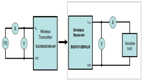
Hi team i need to test receiver ICs BQ51013B and BQ51051B which are WPC 1.1 WPC v1.2 complaints i am trying to get a transmitter EVM for testing this but i am unable to find active EVMs on ti website can you please suggest the Transmitter part number which is active and available in stock.

Thank you

  • Hi Narendra,

    Let me reach out to you offline regarding this request. 

    Best Regards,

    Anthony Pham

  • Hi Anthony offline means

  • Hi Narendra,

    Email, I've reached out to you there.

    Best Regards,

    Anthony Pham

  • My application is to develop a wire-less charging ckt for IoT based system(This much info I can provide)

    Please clarify me below details:

    1.Whether suggested transmitter complies with the both BQ51051BRHLR&  BQ51013.

    2.Is BQ50002AEVM-607 is same as BQ500210EVM-689 since in receiver datasheets they are suggesting HPA689( BQ500210EVM-68)transmitter.

    3.What is the lead time for the BQ50002AEVM-607 since it showing not available everywhere in the Indian distributor’s.

  • Need how much lead time to get this module the shared link by u is not working to buy

  • Hi Narendra,

    Apologies for the delayed reply but I have replied over email. Let us continue there and I can close this thread.

    Best Regards,

    Anthony Pham

  • Hi Pham thanks for your inputs.

    Now  I was able to transfer the power,  Issue is previously position of RX coil not matched properly now it is working fine .

    Since the maximum efficiency is limited to 70%, but in my design we need to put the RX coil few mm away from the transmitter can you please suggest how can I improve the wireless transfer efficiency with respect to the RX coil distance, I mean calculations/ reference document for doing the calculations manually.


    Thanks & regards

    Narendra A

    Hardware Design Engineer.

  • Hi Narendra,


    The main factors for wireless transfer efficiency would be placement and the geometry of the coils. These factors would affect the coupling between the receiver and the transceiver. I’ve been told 50% to 70% efficiency is good coupling. Some thing regarding placement and geometry

    • Field generated by TX should be as undisrupted as much as possible
      • Field can be disrupted by application, PCB, foreign objects, placement
      • This is something for example you may observed based on previous position of RX and new position that allowed for power transfer
    • Coil size and shape should be similar between receiver and transceiver
      • Greater the receiver coil the better but this is space limited by the application
    • It should be noted that all TI RX (and QI systems) have a max coil to coil distance of 5 mm.
    • Efficiency gets getter as load on the receiver increases as there is an initial power consumed to generate the field for power transfer


    Thanks and Regards,


    Anthony Pham

  • Hi pham with the below set up i was able to calculate the efficiency which shown in below table. I am getting over all efficiency of  max 42% even i make load as 800mA,  i am thinking reason is the RX coil size or anything else limiting the efficieny..?

    1. I am able to align the  receiver coil to the transmitter coil and power transfer established properly.

    2. RX coil specifications are 

    BQ5103 output Curren limit  800mA

    Resistive Load (Ohms)

    V_in
    (V)

    I_in
    (A)

    V_out
    (V)

    I_out
    (mA)

    Efficiency
    %

    Remarks

    50

    5

    0.34

    4.948

    100

    29.1058824


    45

    5

    0.37

    4.943

    111

    29.658


    40

    5

    0.36

    4.937

    125

    34.2847222


    35

    5

    0.39

    4.926

    142

    35.8713846


    30

    5

    0.4

    4.918

    176

    43.2784


    25

    5

    0.45

    4.902

    196

    42.7018667


    20

    5

    0.59

    4.877

    244

    40.3385763


    15

    5

    0.75

    4.836

    326

    42.04096


    10

    5

    1.005

    4.28

    450

    38.3283582

    Not able to transfer continuosly

    9

    5

    0.995

    4

    470

    37.7889447

    Not able to transfer continuosly

    8

    5

    0.94

    3.32

    465

    32.8468085

    Not able to transfer continuosly

    7

    5

    0.92

    2.96

    465

    29.9217391

    Not able to transfer continuosly

    6

    5

    0.915

    2.6

    455

    25.8579235

    Not able to transfer continuosly

    5

    5

    0.95

    2.2

    455

    21.0736842

    Not able to transfer continuosly

  • Hi Narendra

    I am assisting Anthony on  this one.

    The Coil is a good one we have used before, see TIDA-00318.  But it will work best at low power <500mA output current.  For higher current a larger coil will work better similar to Wurth 760308103202.

    Above data looks odd, input current seems to limit to 1A above a load to 10 ohms.  Is this possibly a test set up issue?

    Also check the voltage at BQ51013B ISET pin, at 1.2V it will limit output current.