This thread has been locked.

If you have a related question, please click the "Ask a related question" button in the top right corner. The newly created question will be automatically linked to this question.

UCC256404: startup problem if using high value secondary side capacitor

Part Number: UCC256404

DC-DC Design: 390VDC-->+-70VDC (1000W)

The circuit is starting up correctly when secondary load at +70V and -70V Output is 100uF and 50Ohm each.

The cirquit does NOT start up if using 1000uF Caps and 50 Ohm load at each out (1 sec. timeout for restart try).

There is NO start up at  no or very low load condition.

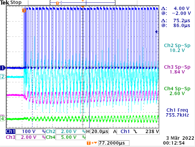
If no start up: ISNS becomes extremely high, see measurement pic. Signal Traces from up to down (measured at UCC256404 pins, short GND):

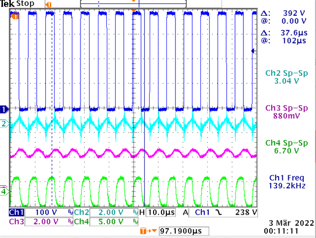
SW (blue), ISNS, VCR, BW (green)

Switching freq. is 100kHz/goal. In reality it starts at approx. 200kHz at startup.

I use UCC25640x Design Calculator Rev4.0.

Resonance and main transformer inductivty is checked and ok (no saturation effects).

Last test I used Option 7 for LL/SS Pin.

Startup allright, and steady stare running at 137kHz, Load 800W (100uF Caps at outputs)

Do you have any ideas how to proceed please? Thank you very, very much. Thomas

  • Hi Thomas,

    Thanks for reaching out to us.

    Could you share the design calculator and schematic with me. To avoid the over current limit during startup, its recommended to increase the start up frequency.

    So,  you can try increasing the Cllss capacitor (up to 2.2uF) and VCR lower capacitor so that startup frequency will be higher. 

    Burst mode disable make the converter output voltage high. You can try option 5 at LLSS pin.

    Could you also tell me the end application and the company name and number of samples you would be needing per year.

    Regards

    Manikanta P

  • Dear Manikanta Thanks a lot for the fast response. I allready increased Css from 100nF (from calculastion) stepwise up to 1uF and this was a bit sucessfull but not enaugh for to hadle 2x1000uF at Out. Opt. 5 I had as default condition additinally. Then I changed to opt.7 for a test -but no startup behaviour change success.

    Increasing Cvcr low (and Cvcr high) did not help either - it seams that maybe other problems occour. At the moment Cvcr high=68pF, Cvcr low=10nF for best starting behaviour at 2x100uF and 2x50 Ohm load conditon.

    Could you please explain the meaning of the "SS initial voltage" (in doc SLUA966A) deeper? How can wereduce the huge starting current  AND mayby go not to hight with the frequency?

    Pls see a measurement inc. the SS/LL voltage (=ch4, green), corresponding to the measurements I sent yesterday:

  • Add-On (because of editing difficulties): Pls see the voltage at pin LL/SS at ch 4 (green trace) during non successfull startup. Switching periode at first start pulses is always approx. 5 micro sec.:

    End Application is planed to be the usage in very high audio power amp product in larger volumes (if successfull).

    Thanks again, Thomas

  • Hi Thomas,

    Could you share the schematic and design calculator. I could run few simulations.

    Regards

    Manikanta P

  • Yes shure - but pls tell me how? xls is 2.6MB. sch is pdf. (sorry -problems with this editor) Thanks a lot!

  • You should be able to upload here.

    Go to insert--> upload file

    You can also share directly to me through e2e private message.

    Regards

    Manikanta P

  • does not work... I sent an email to yout ti account. Thanks

  • Hi Manikanta  Pls see the waveform at LL/SS pin in my last post: green trace, 500mV/div, "option 5" assembly using 220k to RVCC and 100k to GND and 620nF or 1uF to GND. No successful startup. Stop for 1 sec. after approx 19 pulses. I that what you need?

  • Clearly startup current is very high in the waveform that you have shared. This is what making the controller restart. Let me run simulations and give you new values

    Regards

    Manikanta P

  • Dear Manikanta and/or team  Could you have a look at this problem and the xls calc. I sent? Increasing C_LL/SS to 2.2uF did not change anything at startup. The stop after approx. 19 pulses is unchanged.The starting pulse periode is at 4...5 micro sec. approx.

    One additional idea: In SLUA836A is mentioned to insert a resistor between the mid point of the VCR caps and the VCR-pin for to make the start frequency higher. Could you give a calculation idea for resistor value? Cvcr high is 68pF/1000V/film and Cvcr low is 10nF/film at the moment.

    Thanks for your help

  • Hi Thomas,

    I was out of office due to long weekend here in US. Please allow me couple of days for running simulations. I will get back to you by thursday.

    Adding resistance in the VCR capacitor divider wont be recommended to UCC25640x devices.

    For 40x devices, startup frequency can be increased by the following ways:

    1. increasing the LL/SS capacitance

    2. lowering the VCR lower capacitor

    3. Using option 5 for BMTL/BMTH ratio

    Regards

    Manikanta P

  • Ok - I will try again meanwhile and consider these 3 points. Thanks a lot, Thomas

  • Hi Thomas,

    Since we are discussing over the email, I am closing this thread.

    Regards

    Manikanta P