This thread has been locked.

If you have a related question, please click the "Ask a related question" button in the top right corner. The newly created question will be automatically linked to this question.

BQ24250: BQ24250 charger & BQ27532 Fuel Gauge configuration board not charging Inquiry

Part Number: BQ24250

Hi, TI expert.

The customer has configured the board with the BQ24250 charger and BQ27532 Fuel Gauge, and the charging voltage (USB) is connected, but charging is not working.

Below are more details.

[ under ]

1. Issue: USB power is applied but charging does not work.

2. Phenomenon:

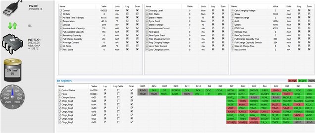
A. Charger Reg1 nCE bit ‘HIGH’ (charge disable) maintained, charge CE pin is connected Low.

B. Command (Charge Enable, Unseal, etc.) was checked with BMS (bqStudio1.3.101), but nCE bit ‘HIGH’ is maintained.
3. Hardware connection


Q1) Please guide me on whether command processing or additional work is required in Fuel Gauge.

Q2) Please check whether the Host (AP) should directly control the Battery Charger BQ24250 with I2C.

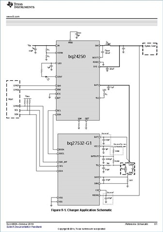
The BQ27532 guide circuit diagram is shown below, and the circuit is configured according to the guide.
Please check.  Thank you.

  • HI Grady,

    The nCE bit must be set to 0 for charging to start.  The BQ25732 is designed to communicate with the charger and enable/disable charge.  The most common issue is a battery temperature fault.  Is the gauge TS pin properly connected to the battery thermistor?  From the GUI, the gauge is reporting temperature -41C, which is a temp fault and so charger should be disabled.  I have copied the gauge temp for further help.

    Regards,

    Jeff

  • Hello Grady,

    What thermistor are you using? Is it a 10k 103AT-2? I can't read the schematic because it is too low resolution. If it is a different thermistor, its possible to change the thermistor coefficients in dataflash to adjust to a certain extent. Please let me know.

    Thanks,

    Alex M.

  • Hi, Jeff , Alex

    Thank you for reply.

    The circuit diagram attached above has been modified so that it can be seen clearly.

    I checked with the customer, but they said that the thermistor was not applied.

    Could it be that the thermistor is not applied, causing the problem?


  • Hello Grady,

    Since it is an NTC, an open circuit will show as an extremely cold temperature. So the thermistor being open makes sense with what we are seeing here (-41C). You should be fine to use the internal temperature sense. Try setting TEMPS in OPconfig to 0 and see if that fixes the issue. 

    Thanks,

    Alex M.

  • Hi, Alex

    The customer company replaces the thermistor resistor, and as a result of checking, it is said to be operating normally. Thanks for your help.