This thread has been locked.

If you have a related question, please click the "Ask a related question" button in the top right corner. The newly created question will be automatically linked to this question.

TPS6594EVM: Power modding / transition between modes.

Part Number: TPS6594EVM


Hello,

I'm looking for hints how to configure properly PFSM in TPS65941212EVM.

Assumptions:

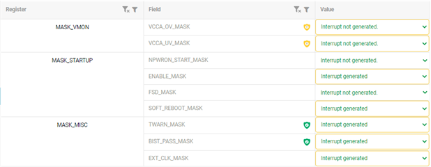
-FSD is ignored (masked)

-First power mode is "Standby"

-Transition to "Active" only when ENABLE=HIGH

-Transition to "Standby" from "Active" is done when ENABLE=LOW


Enable pin is forced in low state by additional PD resistor added on EVM (so default state should be "Standby")


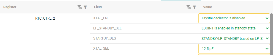
My configuration is following:

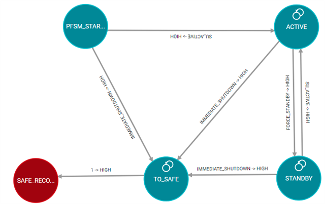
Unfortunately - after programming, when I'm pulling up ENABLE to 5V I can't observe transition to ACTIVE state (I'm checking LDOs/Bucks output)
I checked ACTIVE mode definition separately , by STARTUP_DEST register change to ACTIVE (after this LDOs/Buck are working, so I'm assuming that sequence/outputs are properly programmed).

Any idea what should be changed in PMIC config ?

BR,

Krzysztof

  • Hi Krzysztof,

    I have assigned the thread to the device expert. However, due to the independence day in the US the reply will be delayed. Expect a reply later this week.

    BR,

    Samuli

  • Hello,

    The STARTUP_DEST is standby and not ACTIVE.  Can you clarify what you mean by: 

    I checked ACTIVE mode definition separately , by STARTUP_DEST register change to ACTIVE (after this LDOs/Buck are working, so I'm assuming that sequence/outputs are properly programmed).

    Did you already attempt with STARTUP_DEST=ACTIVE or did you change it during runtime?

    Please refer to this FAQ.

    Regards,

    Chris

  • I tried to set STARTUP_DEST = ACTIVE just to check if output voltages are ok (not in runtime). After this I reprogrammed PMIC, changing this register to STANDBY, because my goal is to have output voltages only when ENABLE trigger occurs, not after First Supply Detection.

    BR,

    Krzysztof

  • Hello,

       The setting of NPWRON_SEL=ENABLE means that the nPWRON/ENABLE pin is configured as ENABLE.  First Supply Detect is only enabled if you select 'None' for the NPWRON_SEL:

    -First power mode is "Standby"

    This is not correct once the PMIC completes BOOT_BIST the first state is the PFSM_START state.  This is where the interrupts are defined.

    -Transition to "Active" only when ENABLE=HIGH

    This is correct.

    -Transition to "Standby" from "Active" is done when ENABLE=LOW

    This will depend upon the trigger priority list.  When SU_ACTIVE goes high this means that the ENABLE_INT is set.  If the SU_ACTIVE is a higher priority interrupt, then it is possible even after the ENABLE pin goes low that the PMIC will not go to the STANDBY state because of the priority of SU_ACTIVE=HIGH being higher than FORCE_STANDBY=HIGH.  In the example below FORCE_STANDBY=HIGH is higher priority.  

    Enable pin is forced in low state by additional PD resistor added on EVM (so default state should be "Standby")

    Are you referring to J45?  You can pull the ENABLE pin low using this jumper or the push button.

    Regards,

    Chris