Because of the holidays, TI E2E™ design support forum responses will be delayed from Dec. 25 through Jan. 2. Thank you for your patience.

This thread has been locked.

If you have a related question, please click the "Ask a related question" button in the top right corner. The newly created question will be automatically linked to this question.

TPS65219: TPS6521901 issue

Part Number: TPS65219

Hi TI members,

i have 2 questions about TPS6521901. from below diagram, we can see for EN_PB_VSENSE ,TPS6521901 is enable, but others support push-button, does it means TPS6521901 can not support HW pull GND to disable this PMIC? if we have push button application, how could we resolve this problem?
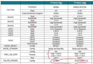
another question, for VSEL_SD_DDR the default config is SD mode, if we want the LDO1 output connect to SOC DVDD1.8V(fixed 1.8V), does that mean, the VSEL_SD_DDR connect to SOC(GPIO), and keep the GPIO low status. so the LDO could output fixed 1.8V?
  • Hello,

    Thanks for reaching out! I have added the responses to your questions below. Please feel free to let us know if you need additional information.

    i have 2 questions about TPS6521901. from below diagram, we can see for EN_PB_VSENSE ,TPS6521901 is enable, but others support push-button, does it means TPS6521901 can not support HW pull GND to disable this PMIC? if we have push button application, how could we resolve this problem?

    Yes; TPS6521901 comes with the "EN/PB/VSENSE" pin configured as Enable with the following polarity: EN=LOW (rails disabled / PMIC in Initialize State), EN=HIGH (rails enabled / PMIC in Active State). Please note this PMIC (TPS6521901 specifically) comes with the FSD feature enable by default. This means the state of the ENABLE pin will be ignored during the first power-up. Once the PMIC arrives to the Active state, then it will start monitoring the state of the enable pin. 


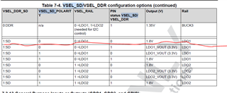
    another question, for VSEL_SD_DDR the default config is SD mode, if we want the LDO1 output connect to SOC DVDD1.8V(fixed 1.8V), does that mean, the VSEL_SD_DDR connect to SOC(GPIO), and keep the GPIO low status. so the LDO could output fixed 1.8V?

    If the output voltage on LDO1 will not be changed between 3.3V and 1.8V then the VSEL_SD pin does not have to be connected to the processor. For example, if the application requires LDO1 to stay at 1.8V then VSEL_SD can be tied low (GND). Please note the max output current on LDO1 is 400mA; Make sure it is enough to supply all the 1.8V rails (from the processor and external if applicable) that will be connected to LDO1. 

    Thanks,

    Brenda

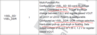
  • Hi before my thinking is to tied resistor low, but i read TPS65219 datasheet. if config VSEL_SD, recommend to connect to SOC, if we choose the hard-wire pull-down, it could be configure VSEL_DDR? so i'm a bit confusion about that.

  • and for EN/PB/VSENCE issue. i know the TPS6521901 support FSD feature, but my concern is if i still want to connect this pin to a push button, when during PMIC active state, does this push button work?

    i don't understand what's the difference between TPS6521901 and TPS6521903 for the pin ' EN/PB/VSENCE' 

  • Hello,

    Below are the answers to the questions in the previous two messages. Please let us know if additional information is needed. 

    Hi before my thinking is to tied resistor low, but i read TPS65219 datasheet. if config VSEL_SD, recommend to connect to SOC, if we choose the hard-wire pull-down, it could be configure VSEL_DDR? so i'm a bit confusion about that.

    [TI response]: The pin function between VSEL_SD and VSEL_DDR is configured at the NVM level. The TPS6521901 was configured for VSEL_SD to control the output voltage of LDO1. Pulling this pin high will set LDO1=3.3V (behaves as bypass and requires 3.3V on PVIN_LDO1) and pulling the pin low will set LDO1=1.8V (behaves as LDO). Our recommendation for connecting the VSEL_SD pin to the SoC is only for applications that will require to change a voltage on LDO1 between 3.3V and 1.8V. 


    and for EN/PB/VSENCE issue. i know the TPS6521901 support FSD feature, but my concern is if i still want to connect this pin to a push button, when during PMIC active state, does this push button work?

    i don't understand what's the difference between TPS6521901 and TPS6521903 for the pin ' EN/PB/VSENCE' 

    [TI response]: Here is an overview of the PB function (more information can be found in the TPS65219 datasheet, section "7.3.3 Push Button and Enable Input (EN/PB/VSENSE"):

    • The power-up sequence can be triggered by pulling the PB pin low (below the VIL-threshold) for the configured tPB_ON (around 600ms. See datasheet for accurate parameter spec). The PB will be needed to wake-up the PMIC if it goes from Active to Initialize state after the first power-on. The other option to get the PMIC into the ACTIVE state would be doing a power-cycle of the pre-regulator to power the PMIC again from "No Power" to "Active".
    • The power-down sequence can be triggered from the Active state by pulling the PB pin low for tPB_OFF-time (around 8s. See datasheet for accurate parameter spec). Just for your reference, the power-down sequence can also be executed through I2C (I2C-command to I2C_OFF_REQ in MFP_CTRL register). Executing a power-down sequence (either by using the PB pin or through I2C) is recommended to make sure the PMIC turns OFF the rails in sequence before the pre-regulator goes below the VSYS UVLO. 

    Thanks,

    Brenda

  • okay, understand, that means if we want to power up the TPS6521903..... we need to add a action that pull PB this pin low around 600ms. and if want to disable also need to pull PB pin low around 8s..... is there an actual application? it maybe just can be applicated on the product which has switch button to control

  • Hi,

    That's correct; Pulling the PB pin low for about 600ms will wake up the device and pulling it low for about 8s will turn OFF the device. PB pin will not be needed during the first power up because of the FSD feature. 

    If the PB pin is not used, it can be pull up to the main supply (VSYS). In this scenario, if the PMIC is sent to Initialize state and there is no push-bottom, then the enable pin of the pre-regulator that supplies VSYS/PVIN_Bx could be used to power cycle the PMIC and send it back to Active state. 

    We also have technical documentation at ti.com that can be used as a reference when designing for power solutions that have push-bottom for enable and disable. Here is an example: Push-Button Circuit (Rev. B)

    Table 3-1 in the applications note "Powering the AM62x with the TPS65219 PMIC (Rev. A)" has attached the design files for the AM62-SK EVM that can be used as a reference. 

    Thanks,

    Brenda

  • Thank you very much!!!