This thread has been locked.

If you have a related question, please click the "Ask a related question" button in the top right corner. The newly created question will be automatically linked to this question.

TPS6594-Q1: VSYS OV and VCCA OV questions

Part Number: TPS6594-Q1


Dear team,

1. We have the System Supply Voltage Monitor function as below. When VSYS_SENSE >6V, the mosfet between VSYS and VCCA will be disconnected. My customer has a question for this question. VSYS connects to pre-regulator's output, and pre-regulator's output is 3.3V, so it is impossible for its output to exceed 6V. Therefore they are wondering what fault would make VSYS exceed 6V? Could you please give us the fault condition?

2. I noticed there are two different thresholds for VCCA's UV/OV. For example, 9.5aa said that the OVP threshold is 3.9V, but in our NVM setting, VCCA_OV is 10% which means the threshold is 3.3+0.33=3.63V. I don't know which threshold is correct? It seems that 9.5aa and 9.5ab specs have no use. Could you please help analyze why we have two thresholds here and how to use them?

Thanks & Best Regards,

Sherry

  • Hello Sherry,

    Therefore they are wondering what fault would make VSYS exceed 6V? Could you please give us the fault condition?

    This condition would be a fault within the pre-regulator in which VSYS is connected directly to the VBAT (high-side FET fails short).

    2. I noticed there are two different thresholds for VCCA's UV/OV. For example, 9.5aa said that the OVP threshold is 3.9V, but in our NVM setting, VCCA_OV is 10% which means the threshold is 3.3+0.33=3.63V. I don't know which threshold is correct? It seems that 9.5aa and 9.5ab specs have no use. Could you please help analyze why we have two thresholds here and how to use them?

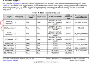
    There are two different thresholds and two different interrupts: VCCA_OV_INT and VCCA_OVP_INT.  VCCA_OV_INT is configured as mcu error while VCCA_OVP_INT is configured as a severe error.  In the event of the severe error the PMIC will use pulldowns to turn off all regulators as quickly as possible.

    Regards,
    Chris

  • Hi Chris,

    Thanks for your reply!

    1. The screenshot you showed is the user guide for 1213&1111. Do we have such user guide for 1515?

    2. For UV/OV detection, do we have deglitch time? I don't see such specs in the datasheet which means our device will report error once the voltage exceeds the threshold, no detection deglitch time? But this will increase the risk of false trigger.

    3. There is LDOVINT over- or under-voltage. My customer wants to know that under what circumstances this error will occur?

    4. SPMI is used in multi-PMIC Synchronization, so there will be no SPMI communication error for TPS65941515-Q1, right? 1515 is the only PMIC to power 821.

    5. There is one error "Main clock outside valid frequency ". Could you please tell me what the function of main clock is? There are several clocks, I am not sure which one is the main clock.

    6. In 1515 NVM, 0x018=011b, which means the threshold is -5%/-50mV. BUCK1=0.8V. 0.8V*5%=40mV. Which is the correct threshold? 5%(40mV) or 50mV?

    LDO1_UV_THR has the same issue.

    7. I have a 1515 NVM excel which is updated in April this year. Is it the latest version? If not, could you please help share me the latest version.

    Thanks & Best Regards,

    Sherry

  • Hello,

    1. The screenshot you showed is the user guide for 1213&1111. Do we have such user guide for 1515?

    I do not.  I will reach out to the applications engineer support this device and see if a draft copy is available.

    2. For UV/OV detection, do we have deglitch time? I don't see such specs in the datasheet which means our device will report error once the voltage exceeds the threshold, no detection deglitch time? But this will increase the risk of false trigger.

    Yes.  

    3. There is LDOVINT over- or under-voltage. My customer wants to know that under what circumstances this error will occur?

    This would most likely occur if the decoupling capacitor on LDOVINT is not properly sized or not properly placed on the PCB. 

    "The LDOVINT voltage regulator is dedicated for internal use only, and cannot be used to support external
    loads. An output filtering capacitor must be connected at the VOUT_LDOVINT pin. Do not connect any other
    components or external loads to this VOUT_LDOVINT pin."

    4. SPMI is used in multi-PMIC Synchronization, so there will be no SPMI communication error for TPS65941515-Q1, right? 1515 is the only PMIC to power 821.

    This is correct.  The SPMI is disabled for the TPS65941515-Q1.

    5. There is one error "Main clock outside valid frequency ". Could you please tell me what the function of main clock is? There are several clocks, I am not sure which one is the main clock.

    There are two 20Mhz clocks for redundancy and then another 128Mhz clock to confirm that the 20Mhz frequency is correct.  The 20Mhz is the basis for the BUCK switching frequency.

    6. In 1515 NVM, 0x018=011b, which means the threshold is -5%/-50mV. BUCK1=0.8V. 0.8V*5%=40mV. Which is the correct threshold? 5%(40mV) or 50mV?

    When the output is less than 1V then the threshold is -50mV.  When the output is greater than or equal to 1V then the threshold is 5%. 

    7. I have a 1515 NVM excel which is updated in April this year. Is it the latest version? If not, could you please help share me the latest version.

    I believe you are aware of the changes made last month, but the Excel would not be impacted by these changes (none of the rail sequences have changed).  I will confirm with the engineer supporting the1515.

    Regards,

    Chris

  • Hello Sherry,

    I have emailed you a draft for the 1515 user guide.

    I do not have a latest version of the excel file, but user guide includes updates to the NVM statics from Rev 1.

    -Mike