This thread has been locked.

If you have a related question, please click the "Ask a related question" button in the top right corner. The newly created question will be automatically linked to this question.

BQ25720: reduce peak charging current

Part Number: BQ25720

Hi team,

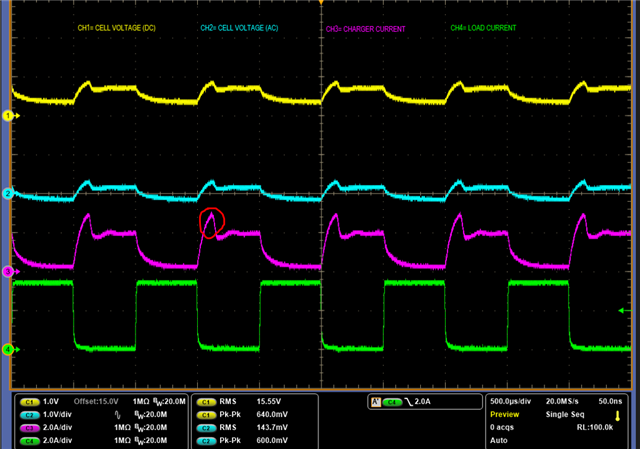
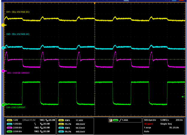
when customer performed the system load transient, you can see channel 3  the charge current has a prominent peak,

I know during input current limit, the BATDRV keep same voltage all the time , so I suspect this peak current may be caused by Vsys peak as you can see from channel 1 or 2.

would you let me know how to minimize this peak current ? 

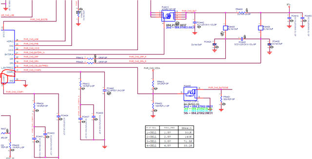
should we start from COMP component? 

  • Hello Fred,

    There are multiple loops inside the charger, for example, input voltage, input current, system voltage, charge current, charge voltage etc. To simplify the design process, TI provides two sets of compensation network. These compensation values have been verified by design, and validated during the product development process, at different input  and with different battery cell configuration. There is no benefit to further optimize the compensation networks.

    Therefore, it is NOT recommended to change the compensation values in the buck-boost charger. 

    Just to make sure to meet the minimum input capacitance requirement (table) and minimum output capacitance requirement (table) in your application.

    Thanks,

    Khalid

  • Hi Bairuti,

    1. Capacitance after RAC before power stage half bridge is  100nF+10nF+1nF instead of 10 nF + 1 nF as datasheet listed,

    could this potentially be a problem?

    I see nine 10uF MLCC at output, which is sufficient for 65W design,

    so is the input cap (10uFx6)

    do you think there's other cause?

  • Hi Fred,

    I recommend to match the datasheet recommendation for these capacitors especially since it says "Capacitance after RAC before power stage half bridge should be limited to 10 nF + 1 nF."

    In terms of the current spikes seen on IBAT, it should be due to the SYS peaks. This charger has a feature to limit IINDPM spikes so that the adapter does not see these current spikes and sees a smooth ramp up. Have you monitored the Input current to see if there are spikes in that waveform? 

    Thanks,
    Khalid

  • Hi Khalid,

    would you help check internally why datasheet recommend  exact 10nF+1nF instead of larger cap ,since larger cap normally is better in most case?

    customer wants to know the reason before they will modify it.  

    please help explain why larger cap there will cause this peak charging current, thanks

    thanks 

    Fred

  • Hi Fred,

    This circuit is a current sense amplifier and used to monitor input current. More capacitance on those lines can filter out the input current intended to be sensed. It is difficult to determine whether this is the root cause or not, but we should follow the guideline in the datasheet as this is what was verified and characterized. 

    Also, can you confirm if filters on ACN/ACP and SRN/SRP are correct and populated?

    Thanks,
    Khalid

  • Hi,

    per checked, ACN/ACP and SRN/SRP looks ok, but you may check again,

    BTW, they didn't differentiate AGND and PGND, and I'll ask them to change,

    but as far as I know ground partition has nothing to do with the issue we're having here, right?

    please help check internally, thanks

    Regards,

    Fred

  • Hello Fred,

    The filters look good.

    The AGND/PGND separation should have no impact on this issue.

    Thanks,
    Khalid

  • Hi Khalid,

    after customer removing PC4416, keep only 10nF and 1nF,

    the response seems smoother compare to previous one but the peak is still there,

    is this expected result ?

    if not, what's our next step to debug?

  • Fred,

    The behavior is expected however I can't quantify what the magnitute of the spike could be since the hardware is custom. I would recommend the customer try the same test on EVM and compare result to their board.

    Thanks,

    Khalid

  • Hi Khalid,

    I just test EVM,

    the peak current is also occurred, so I guess this is expected phenomenon . (yellow is Vsys, blue is charge current)

    But can this ringing be reduced if I add more cap at Vsys?

    since the root cause is the ringing from Vsys.

  • Fred,

    More capacitance at VSYS should reduce the impact, yes.

    Khalid

  • thanks

    do you prefer additional 100uF or 0.1uF ?

    I supposed this high transient response , I should add more 0.1uF,  right?

    how about the parasitic that cause this LC damping

    Regards,

    Fred

  • Hi Fred,

    For HF noise we should add more 0.1uF close to the VSYS. 

    By the way, during this testing, is the customer using an actual Battery, or at least using a large capacitor to simulate a Battery?

    Khalid

  • they use real battery,

    we'll try 0.1uF cap to see how it goes, thanks