Because of the holidays, TI E2E™ design support forum responses will be delayed from Dec. 25 through Jan. 2. Thank you for your patience.

This thread has been locked.

If you have a related question, please click the "Ask a related question" button in the top right corner. The newly created question will be automatically linked to this question.

BQ25708: REGN drops out periodically

Part Number: BQ25708

Hi,

I got an issue with the REGN pin periodically dropping, with the charger chip also rebooting and losing all the configurations.

The REGN pin is driving nothing except for the VDDA pin and two resistors (100Kohm and 59Kohm) to set ILIM_HIZ. on the output there is a 2.2uF 16V ceramic capacitor. Derating with DC bias for 6V gives leaves me with 1.98uF

There is no way I am exceeding the 50-60mA current limit.

What else could be causing the regulator to be overloaded?

  • If it helps, the circuit is using the following FET's:

    for the 4 NFET's https://www.ti.com/lit/ds/symlink/csd17327q5a.pdf
    for the PFET www.vishay.com/.../si4435fdy.pdf

  • Hello Andre,

    You mentioned you have 2.2uF capacitor on output for REGN. Do you also have the recommended 1uF capacitor on VDDA?

    What VBUS voltage are you using when you experience this dropout and does it happen at any VBUS you use?

    Thanks,
    Khalid

  • Yes the 1uF is there as well.

    I haven't tried other voltages, but the one I'm testing with is 20V and outputting either 8.4V or 16.8V depending on what it is instructed but the monitor microcontroller.

  • Hi Khalid,

    I have tested the circuit with input voltages of 5V, 9V, 12V, 15V and still REGN will periodically drop out.

    An identical circuit on the same board works perfectly however.

  • Andre,

    Is the CHRG_OK high after power up?

    How often does the dropout occur and is it periodic? Have you disabled the watchdog timer?

    The charger includes watchdog timer to terminate charging if the charger does not receive a write MaxChargeVoltage() or write ChargeCurrent() command within 175 s (adjustable via REG0x12[14:13]). When watchdog timeout occurs, all register values are kept unchanged except ChargeCurrent() resets to zero. Battery charging is suspended. Write MaxChargeVoltage() or write ChargeCurrent() commands must be re-sent to reset watchdog timer and resume charging. Writing REG0x12[14:13] = 00 to disable watchdog timer also resumes charging.

    I would also recommend to monitor VBUS on a scope to see if anything is drooping when the dropout occurs. 

    Hope this helps,
    Khalid

  • Hi Khalid,

    The CHRG_OK pin is solidly high at 5V (my pull-up voltage).

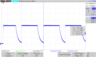
    The dropout is periodic with a period of 184ms. REGN is held low for 50ms exactly. For the remaining 134ms REGN is at 6V exactly. I have also attached a screengrab of the oscilloscope for your reference.

    Register ChargeOptions0 has a value of 0x150B which should put the WDTMR_ADJ bits to 0b00 disabling it.

    VBUS is solid at 20V and there is no output voltage from the BATFET.

  • Hi Andre,

    Thanks, those timings may help us understand what's going on. Based on below sequence, my assumption is that when the converter powers up, some fault is causing it to reset.

    The power-up sequence from DC source is as follows:
    1. 50 ms after VBUS above VVBUS_CONVEN, enable 6V LDO and CHRG_OK goes HIGH
    2. Input voltage and current limit setup
    3. Battery CELL configuration
    4. 150 ms after VBUS above VVBUS_CONVEN, converter powers up.

    Based on the conditions you described, I don't see a specific fault condition that explains your situation, however, it would be good to confirm these - ACOV, ACOC, SYSOVP, BATOVP, Battery Short

    Can you read back the ChargerStatus register (0x20h) to see if there is any fault condition observed?

    Thanks,
    Khalid

  • Hi Khalid,

    Thanks for your reply.

    So if I understand correctly the issue is cropping up at the converter's power up (step 4)?

    Unfortunately I had already tried reading these values after the reboot sequence - but it seems that they all go to their reset value. So there would be nothing useful in these registers.

    Is there anything else I can check?

    Thanks

  • Hi Andre,

    Yes that seems to be the case. In an earlier response, you mentioned "An identical circuit on the same board works perfectly however." Can you explain this? Does that mean this design is working elsewhere but this specific board is not working?

    I would suspect an issue in schematic or manufacturing that is causing the converter to shut down, possibly with a pin not making contact, or the inductor or one of the FETs. It would be good to check the connection on all of those components, as well as monitor SW1/SW2/VSYS/BATDRV for any abnormal behavior.

    Can you share a schematic for me to review?

    Thanks,
    Khalid

  • Hi Khalid,

    It could be the case, but with a pass rate hovering around 25% I'd say there must be some other explanation as well.

    Please find attached the schematic of the charger section.

    In the meantime I will also monitor the FET drives for any abnormal behaviour.

    MiniDV Charger-2.pdf

  • Hi Khalid,

    It seems I measured the CHRG_OK pin incorrectly - actually the CHRG_OK signal falls low when the REGN Voltage falls.

    Thanks and regards

    Andre

  • An identical circuit on the same board works perfectly however."

    The design utilises two charger IC's coordinated by an MCU.

    One can have one board with both charger IC's working perfectly (albeit a bit too hot), another with one side with this issue, another with the other side having this issue - or others with both sides having this issue.

  • Andre,

    Thanks for the additional details and the schematic. I'll look over your schematic tomorrow and let you know if I find anything.

    Khalid

  • Andre,

    I reviewed your schematic and was comparing to our EVM schematic. I only found one issue - the resistor on the IADPT pin is 100KOhm, but you are using a 2.2uH inductor. The inductor value is sensed using this resistor. For 2.2uH we should use 137kOhm resistor. I believe with the 100KOhm the device thinks you are using a 1uH inductor. This could explain why the converter shuts down and also why it happens on some boards vs others (I am not sure what tolerance resistor you are using there.

    Could you try to replace this with a 137K resistor and see if it fixes the issue? I recognize there is a datasheet typo on page 5 in the pin descriptions that says "For 2.2uH, the resistor is 100KOhm". This needs to be fixed.

    Let me know if that fixes your issue.

    Thanks,

    Khalid

  • Hi Khalid,

    I currently do not have 137kOhm resistors in hand, but made do with 160k and 1Meg in parallel. The combined resistance is 137.9kOhm.

    However, the issue remains identical.

    What else could I check?

    Could the gate charging current be triggering the dropout on REGN?

    Thanks and regards,

    Andre Cilia

  • Hi Andre,

    OK, it's unfortunate that that didn't fix the issue but it should be addressed regardless.

    At this point I don't see any other issue with the schematic so I would recommend you start to isolate components (start with the FETs and inductor) to see if swapping between a "good" board and a "bad" board follows the component. This would help narrow down the issue.

    Thanks,
    Khalid

  • Hi Khalid,

    I have noticed that replacing the FET driven by LODRV1 (Q9 in my provided schematic) sometimes helps.

    If Q9 is for whatever reason damaged and shorted to ground (we are doing a first production run and we had some other modifications that we had to do), shorting SW1 to ground continuously. Would such a situation give this issue?

    Regards,

    Andre

  • Andre,

    That is a possibility. I will try to replicate that behavior on Monday and let you know what I find. I don't see anything wrong with the Q9 FET you have selected so it could be a short as you mentioned.

    Khalid

  • Hi Khalid,

    Is there any update with regards to this issue?

    Thanks and regards,

    Andre

  • Andre,

    I set this up on my bench and saw similar behavior, however it was not exactly replicated. I see REGN drop out for 50ms, but then the total period is 1.84s instead of 184ms. I am not sure what causes that difference but it could just be a configuration difference between your board and my EVM.

    This behavior occurs whether I short LODRV1, LODRV2, HIDRV1, HIDRV2, or BATDRV to ground.

    I think then that your issue should be related to one of those FETs during fab / assembly / rework.

    Thanks,

    Khalid

  • Hi Khalid,

    My observations is that the short to ground isn't with the LODRV1, HIDRV1, LODRV2 or HIDRV2 pins. The short I have observed essentially shorts pins SW1 and SW2 to ground through the FETs driven by pins LODRV1 and LODRV2.

    Can this difference explain the timing difference you are noticing?

    Best regards,

    Andre

  • Andre,

    I had another issue with my setup that was causing the ~2s period. Today I also tried to reproduce SW1/SW2 nodes short to ground and they don't replicate the behavior you see. However, I shorted BTST1/2 to GND and I see the REGN drop out every ~180ms like you do, but REGN does not make it all the way up to 6V. I think your issue definitely has to be near the inductor or the FETs but I am unable to replicate it on my setup. I would recommend to scope out the signal you see on each of these pins (LODRV/HIDRV/SW) to further isolate the issue

    Khalid

  • Hi Khalid,

    With this new information at hand I will therefore submit a new slightly modified design correcting all the issues we had in this first version. In this way there shall be no manual interventions on these newer boards required.

    If what you are suggesting is correct, we should not be seeing these issues with the new design.

    Am I correct?

    Thanks and regards,

    Andre

  • Andre,

    I agree that it seems the manual modification of the board is causing some issues.

    I had reviewed your schematic and don't see any issue there. Please also make sure you are following our layout guidelines on page 67 of the datasheet.

    Thanks,

    Khalid

  • Thanks.

    I will revert with any updates once the newer boards are in hand

    Thanks and regard,

    Andre