This thread has been locked.

If you have a related question, please click the "Ask a related question" button in the top right corner. The newly created question will be automatically linked to this question.

LM27402: Strange behavior in the cold

Part Number: LM27402
Other Parts Discussed in Thread: LMZ31520

I'm seeing my LM27402 circuit exhibit odd behavior at very cold temperatures. At -40C, the circuit comes up but is delivering significantly lower than the set voltage, usually around 2.8V for my 3.3V design. 

Not shown, but we seem to periodically get into a state where the switch on time is very short, there are large hiccup gaps, and the voltage drops even lower, below 2V. This looks a reset of the controller of some sort, a bit like the way an overcurrent event is described, but we're at a very low current at this point in the system, and there's not a huge current inrush, as this regulator, my main 3.3V supply, is taking over part of the system from a linear pre-boot power supply.  

As we get to around -22C, the regulator hits normal regulation and the unit comes up fine. 

Another odd thing we found by accident. One of my guys had put a direct 50 ohm probe on the CS+ node... I didn't notice the type, given the test unit being in the temp chamber and all. With that probe attached to our scope, we stopped falling into the long hiccup/reset mode periodically. 

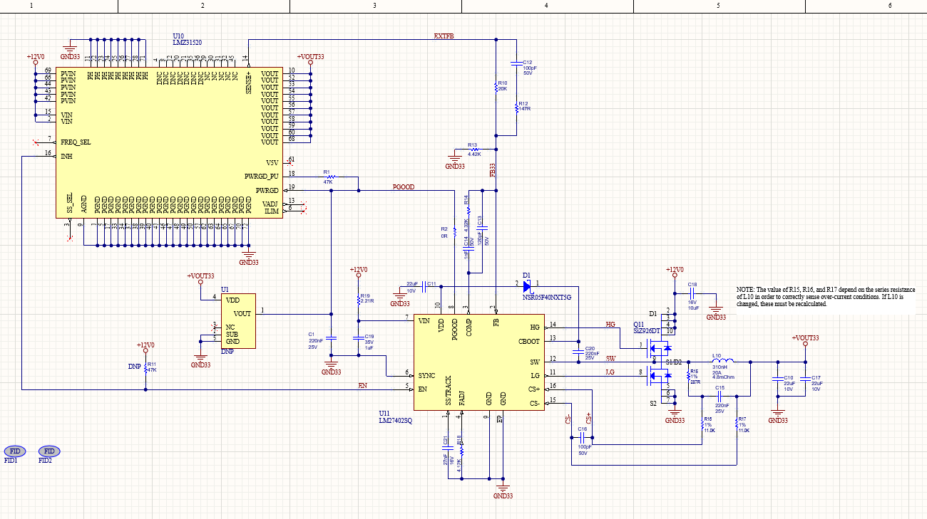
Here is the schematic. This is an LMZ31520 replacement module, so the LMZ31520 isn't an actual chip, and there is considerably more external capacitance surrounding this unit, as well as a completed feedback loop from the output via EXTFB on my main board. 

So any suggestions at tweaking away this cold sensitivity are greatly appreciated. 

  • LM27402DesignCalculator_frog.xls

    I reviewed the information and entered the schematic values into an excel sheet (attached) to check the loop stability.   

    I get a crossover frequency of 85kHz and a phase margin of ~40 degrees.    The goal would be to have a phase margin greater than 45 degrees. 

    The Cout of 2x22uF 10V  ceramic capacitor will derate to ~14uF of capacitance each when operating with dc bias of 3.3V.  

    At 40 degrees phase margin the converter would switch and look stable in steady state.   I think maybe the temp change is enough to make the converter unstable.   What is the off sheet capacitance on the output.  

     Can you investigate the loop stability, by making some component changes. 

    For troubleshooting can you change the following components and then take the temperature down and check regulation. 

    Change 1000pF to 2200pF and  Change 4.32kOhm to 2.61kOhm  

    These changes will lower the crossover to 73kHz and increase the phase margin to 60 degrees.   Any component variation from temperature should not make the converter unstable with these feedback components. 

    Is there additional input bulk capacitors, a single 10uF is not much capacitor.  I estimated an output current is 20A, from the rdc of the inductor and current sense resistor.  If the output current is 20A, the input rms current will be about 9A.   The 10uF capacitor's rms current rating is about 3A-4A.  Additional input capacitor may be needed. 

    I am not sure on the 50 ohm probe connection, if the above component change does not improve the issue.  I suspect there is noise causing the oc to trip.   Can you share the pcb layout. 

  • Thanks for the quick response. 

    I have additional 300uF Tantalum and 94uF Ceramic on the module input, same on the output.  This has been extremely reliable in a product we delivered in 2020 using the LMZ3150, but I'm sure you're quite familiar with parts supply issues in 2022. 

    Here is the PCB/Assembly file.

    Interposer-LMZ31520_33V_revB_Assembly_Drawings.PDF

  • Thanks  I am reviewing the layout and will have some suggestions tomorrow.

    One question I have is are the pins 22 to 28, 71 of the LMZ31520 connected to ground?

  • On the actual board's footprint for the LMZ31520, pins 11, 22-28, and 71 are connected together, but not to ground. Grounding those on this module was just to simplify layout. 

    An update. We tried the new values, C14 = 2200pF, R14 = 2.61K ohms. This had only a small effect on operation at -40C. The regulation was varying between 2.7V and 2.9V most ot the time, averaging 2.8V or so, never locking in at 3.3V. We did not, however, see the odd periodic reset that we had always seen. Operation is still stable at -20C up to 70C (we've been chasing an unrelated issue at 70C, so these units have been through the full spectrum of testing).  There was some question if we had an NP0 cap for the 2200pF for more temp stability, versus an X5R or X7R. I don't know which was used in the test. 

    If you have any place I might look next, I'd be obliged. Thanks. 

  • Make sure the SS pin is greater than 0.6V during the test.    The device will use the SS pin as a reference if the voltage is less than 0.6V.  

    The feedforward circuit and current limit can terminate the sw pulse width and cause the output to droop.

    The VIN pin is used to set up a feedforward ramp and the bias supply VDD.     The VDD bias supply sources the gate drivers. . The switching of the power fets may be causing noise on the VIN.    The feedforward ramp is part of the control loop.    

    If the VIN pin is noisy, the ramp is noisy and maybe causing the sw node to terminate early.     

    To troubleshoot the feedforward ramp hypothesis, if there is a way to connect a capacitor directly to VIN (pin 7) to GND (pin 9)on the top side without using vias. 

    The current limit can cause the output voltage the droop or hiccup.     If there are 5 OC events in 32 cycles the device will shutdown for 1.28ms (hiccup).

    The OC counter is reset if there are 32 consecutive switching cycles without an OC.     Hypothetically, If there is noise causing a high side fet to terminate early and not enough OC events to enter hiccup then the output would droop but not shutdown for the hiccup.   Since the operation is at light or not load,  it is unclear how the device is  would be triggering the OC.   The LM27402evm pcb layout has the  100pF for CS+ and CS- close to pins and the Rset further away from the pins.    On your layout pcb layout, R17 is next to the inductor and CS- pin, is it possible that the inductor field is causing OC to trip. 

    Has the 100pF on CS+ and CS- been increased during the troubleshooting.         

  • We have not boosted the 100pF cap yet. It's easy enough to boost that, and add another cap from pin 7 to pin 9. 

    I'm wondering if we can temporarily disable the current sensing (pull R16 and R17) just to have an idea if that's part of the problem.

    I was also concerned that perhaps we're at an edge-case on minimum load when we get that cold, so we're taking a look at adding a small load to see if that has any effect. 

  • I like your ideas.   I think shorting the 100pF will be a way to defeat the OC to troubleshoot, CS+ and CS- will be at same potential.     

    Minimum load edge case may be valid, but it is unclear to why this would cause an OC fault. 

  • Once we changed the loop filter, we weren't seeing the shut-down that I took to be an OC fault. Though they didn't have a probe on the switch node to know for certain, when we tripped whatever fault we were seeing, it looked like the chip rebooted, power dropped back to nearly nothing. Thanks... I think my boys will be trying these things out today.

  • Any chance we could schedule a Google Meet with you for 1/2 hour or so? 

  • Yes, I can.   Accept my friend request in this system and then send a private email using this system on the details or I can send a webex invite if you sent a email address.   

    I am available at 4pm CDT today and nearly anytime tomorrow. 

  • closing working directly offline