This thread has been locked.

If you have a related question, please click the "Ask a related question" button in the top right corner. The newly created question will be automatically linked to this question.

TPS2597EVM: TPS25970ARPW

Part Number: TPS2597EVM
Other Parts Discussed in Thread: TPS2597

Hi,
I need some protection for a circuit. The input power source is four AAA battery to provide 3V and 2400mAh input to the circuit.
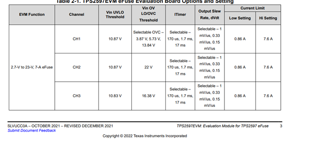
The load current will not be more than 1A so i need help to select external components for the TPS25970ARPW.

I am bit confused with the terms used in the datasheet. So plz help me to define resistance values and capacitors values.

DATA:

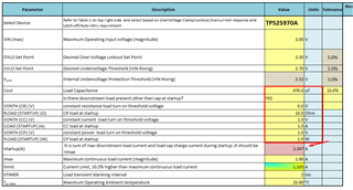
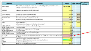
Input Voltage = 3V (Max 3.3V)
Input Current = 2400mAh ( Limit to 1A)
Output Voltage = 3V
Output Current = 1A

Under voltage = 2.7V
Over voltage = 3.3V
Over current = 1.2A


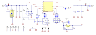
Also, i want to keep the BOM as small as possible so Can i ignore TVS diode and Schottky Diodes mentioned in schematic.

Thanks

  • Hi Ali,

    1. Please use design calculator on product page of TPS2597 on TI website to calculate external components. You can input requirements and calculator will show values of components. You can also refer application section in datasheet to understand more.

    2. Refer this link to understand some terminologies in datasheet-> e2e.ti.com/.../faq-tps25947-understanding-common-terminologies-used-in-efuse-datasheet

    3. You can ignore TVS. You can also ignore Schottky  if chances of short at output are less in your application. These components help in transient protection. You can read more in datasheet transient protection section.

    Regards

    Kunal Goel

  • Hi,
    I already downloaded it but there are some parameters that I don't know. Also, there is one cell value issue
    Plz, see the attached screenshots.


    1. OVLO SET POINT ( Voltage that should not exceed. Right?)
    2. UVLO SET POINT (Voltage that should not go below it. Right?)
    3. Vuvp ( Predefined and not changeable. Right?)
    4. Cout, VONTH, RLOAD,  (I don't know)

    Also, in the EVM schematic, the fixed resistance values has been used. In that case, what will be the OVLO, UVLO?

    Also, how this IC provide protection against short circuit ?

    Thanks

  • Hi Ali,

    1. These cells are input for different kinds of load during startup. Based on these inputs dvdt cap is recommended for successful startup. Since you don't know them I will recommend you keep a placeholder for dvdt cap and keep it depopulated by default. If you see failed startup later we can add suitable cap there.

    2.  

    1. OVLO SET POINT ( Voltage that should not exceed. Right?) Yes
    2. UVLO SET POINT (Voltage that should not go below it. Right?) Yes 
    3. Vuvp ( Predefined and not changeable. Right?) Yes 

    3. EVM description is in user guide.

    You need to enter UVLO as 2.7 and OVLO as 3.3 in calculator. You can select pullup R1 and based on that R2 and R3 are recommended.

    4. Please read datasheet section 8.3.4.4 Short-Circuit Protection

    Regards

    Kunal Goel

  • Hi 
    Thanks for the above explanation.

    I setup following values for the circuit. Correct me if i am wrong.

    1. ILIM R = 5.6K  to limit current 1A of the circuit
    2. ITIMER C = 220pF to setup response time. I setup it to 170uSec because 1A is maximum the load current and I don't want to exceed current more than that for longer period.
    3. DV/dt just put the place and will see how it work.
    4. R1 = 470K ohm
    5. R2 = 69.8k ohm
    6. R3 = 309K ohm

    Let me know if these are the correct values or if i made any mistake while calculating it.

    Thanks

  • This still giving me error and I don't know how to resolve it because it is not editable cell

  • Hi Ali,

    1. Please attach your filled design calculator in this e2e thread, I will review it.

    2. You have to make other loads zero then red colour will go away. Set RLOAD as some megaohms, make ILOAD and PLOAD=0.

    Regards

    Kunal Goel