Dear TI Forum,
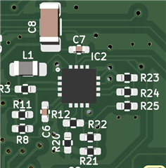
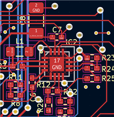
I've made a custom PCB with the BQ25504 energy harvester IC. I use this IC to charge a small LiPo battery. On top of that I have the XB5353A one cell Lithium protection IC. Currently I have tested the PCB while I power it with a USB, all the circuitry seems to work (to power an ESP32, some LEDs and an E-Paper). This is done with a simple FET:

Now I'm trying to power the circuit by a one cell Lithium Ion Battery that is charged up to 4.01V and a 2V solar panel. The BQ25504 datasheets provides a calculation sheet table for all the necessary values for cut-off voltages, under-over voltage etc, I've used these values:

Basically
-
Vbat overvoltage: 4.2 V
-
Vbat OK (output signal): 3.58 V
-
Vbat undervoltage: 3.27
-
For the solar panel the MPPT voltage 2.23V, with the open circuit voltage 2.76V
I've used the closest 1% resistor values. This gives me the following BQ25504 schematic with all the necessary resistor values:

And here the XB5353A LiPo protection schematic part:


This is all the circuitry I have to power it using Vbat. Now when I disconnect the USB. Connect the 4.01V LiPo battery and the 2V solar cell, nothing happens. I measure on the Vstor/V_SOLAR_OUTPUT around 0.8V to 1.2V that is going up and down while I expect around 4.2V.
Now I've been running a lot of tests and in some very rare cases when I'm just constantly plugging in/out the battery and solar panels the voltage on Vstor (V_SOLAR_OUTPUT) suddenly jumps from around ~1.5V to 4.05V and the battery is able to power the circuit! I'm still unsure if this 4.05V is the direct battery voltage, or the supposed 4.2V that seems a little lower. I can then unplug and plug in the solar panel while the battery still maintains to power the circuitry. I am clueless at this point.
What could cause this issue? Have I misinterpreted a datasheet or maybe a mistake in my schematic?
Thanks for any help!


 (LBST green)
 (
( (VIN_DC green, an actual solar cell)


