This thread has been locked.

If you have a related question, please click the "Ask a related question" button in the top right corner. The newly created question will be automatically linked to this question.

LMG3410-HB-EVM: Fault LED on LMG3210-HB-EVM illuminating with no switching action occuring

Part Number: LMG3410-HB-EVM
Other Parts Discussed in Thread: LMG34XX-BB-EVM, , LMG3411R050

Hello,

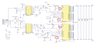
I have set up my power board to use the above half-bridge demonstration board for a PhD project. When I apply a 5V power supply to the demo board, the LED illuminates to indicate there is either and undervoltage lockout, overcurrent or overtemperature event. First of all, I am not actually switching any power - which probably rules out both the overcurrent and overtemperature events since no power dissipation is occurs.

I have measured the voltage at a test pin before it is given to the demonstration board and this measures approximately 5.3V. I'm not entirely sure why this voltage is higher than that of the power supply. 

But I am absolutely perplexed as to why the LED's are illuminating - first of all, if I leave the 12V pin open, because I am only using the 5V supply method for the daughterboard, would this cause the LED's to illuminate since one of the "bias supplies" are detected to be zero? Surely if we are using the 5V supply method, we do not care about what the 12V signal is, whether that be 12V or 0V, because we are not using it - but I am not entirely sure under exactly which circumstances does the demo board output an active low signal?

Is there anything else I am missing that could be causing the LED's to illuminate? The voltage given to the daughterboard is more than required by it - 5.3V as opposed to 5V, so again UVLO does not make sense, but neither does overcurrent or overtemperature since there is no voltage or current applied to the power circuit.

Best regards,
Joel 

  • Hey Joel,

    I just wanted to clarify which components are being used:

    Motherboard: LMG34XX-BB-EVM

    Daughtercard: LMG3410-HB-EVM

    Please advise if these are the correct part numbers for the setup you are using.

    Best regards,

    Kyle

  • Hi Kyle, 

    • thanks for your reply. Actually, I am just using the half bridge HB-EVM which is designed into my own power board. I control the PWM With the F2837xD C2000 DSP. The issue however is something to do with the HB-EVM. 
       

      best regards, Joel
  • Hey Joel,

    Could you check the voltage across the C8 and C23 capacitors and confirm that they are both 12 volts.

    Best regards,

    Kyle

  • I added an image of the schematic with the two capacitors to be measured circled for clarity.

  • Hello Kyle,

    Sorry for the long time it has taken for me to reply but I had a holiday last week. 

    I have tested the capacitors in question I think - but although one is 12V, the other three are more like 15V. I am using two of the boards as I have two half-bridge converters. 

    It is strange that the voltage would be 15V considering the 12V regulator on board. Although I notice that the transformer that creates the 12V from 5V is a 1:3.1 step up transformer. Furthermore the VDD supply is allowed to be as high as 20V as per the data sheet: LMG341xR050 600-V 50-mΩ Integrated GaN Fet Power Stage With Overcurrent Protection datasheet (Rev. B).

    Do you have any suggestions where to go from here?

    I'd also best clarify that my post title is a little misleading - I say there is no switch action occurring but I've not actually tested that because of the illuminating LED's. The data sheet states to not test the switching with any LED's illuminated so I have not attempted to do so. What I meant was that there can't be an Overcurrent or Overtemperature event since I have not enabled the 270VDC input power supply to the converter. 


    Best regards,

    Joel

  • Those values are within reason for those capacitors. The next capacitors I'll have you check are Vneg cap (C9 & C26) and the LDO5V cap (C5 & C7). We are looking for -14 V across the Vneg capacitor and 5 V across the LDO5V capacitor. Also are you able to tell if both EVMs give the fault signal or just one of them?

  • Hi Kyle, 

    I have verified that the VNEG capacitors are both -14V, and both LDO capacitors are showing 5V or thereabouts. Both upper and lower devices, on both boards, have a 5V signal present on their fault signal outputs. This would actually indicate to me, considering the LED circuit on the motherboard, that there actually is not a fault present on the board? With the 5V connected to the top of the LED, and a 5V signal output from the FAULT pins, there should not be any current into the LED. So I am even more perplexed now why they are illuminating. I checked the output of the AND gate and despite both C6 and C11 being approximately 5V, the output of the AND gate is zero. I have checked pin 5 of the digital isolators, which is the OUTC pin, and again all of these are showing HIGH outputs, which indicates there is no fault - I can only assume there is something wrong with the AND gates, but what could possibly be wrong with them?

    I'm not sure what else to check, all bias rails are verified correct, there is no OCP or OTP, but the AND gate doesn't seem to be working the logic we expect it to. I would expect this to be one of the last things to be not working! Let me know your thoughts on the above?

    Best regards,

    Joel

  • If both the fault signals going into the and gate are high then the output should be high as well. Since this is not the case I would check the and gate, making sure it is getting the power needed and has good connection to the board. I would also check the motherboard and make sure that there isn't something on the mother board that is pulling that line low.

  • Hi Kyle, 

    Okay, I think I have found the problem, the pins of the Altium footprint were different to those in my schematic! Looks like I had connected the FAULT signal to ground, illuminating the LEDs constantly.

    Just a quick question on the side if I may - are any of the LMG chips with integrated drivers able to stop switching automatically under fault conditions or is this fault circuit absolutely necessary? From the data sheet, some phrases such as the below indicate that it is an automatic process that the integrated driver shuts down the FET's in case of a fault: 

    "LMG3411R050 provides cycle-by-cycle OCP option. In this mode, the FET is also shut off when overcurrent happens, but the output fault signal will clear after the input PWM goes low. In the next cycle, the FET can turn on as normal. The cycle-by-cycle function can be used in cases where steady state operation current is below the OCP level but transient response can still reach high current, while the circuit operation cannot be paused. It also prevents the power stage from overheating by having overcurrent induced conduction loss."

    In the event of a fault are the auxilliary rails powered down, stopping the FETs from switching? I have actually used this board before, without utilizing the FAULT signal, and if my LEDs were illuminated, even putting a gate drive signal into the FET did not allow them to switch. Could you please clarify exactly what happens in the event of a fault, and is it completely manual and up to the user to ensure the faults are dealt with? There is nothing internal that stops the FET switching?

    Best regards,

    Joel

  • Glad we were able to help resolve that. Our GaN devices do stop switching when one of our fault events is detected. The Fault pin is an output to allow the user to know that a fault has occurred and that the device has stopped switching.

  • Hi Kyle, 

    Thanks for the above information. The data sheet for the daughterboard states the following: 

    "Please do NOT ignore FAULT signal when using LMG341xEVM-018. Turn off both top and bottom devices, if any device is generating FAULT signal. The device under fault condition may operate in undesired 3rd-quadrant mode and may be over heated and damaged due to the high source-drain voltage drop if the other device is still switching"

    Which would indicate that the user is responsible for stopping the switching of the device, rather than the devices automatically shutting off under fault conditions? 

    Furthermore, does the FAULT LED illuminate if there is an issue with the VNEG -14V rail? I have fixed the above issue but for some reason both FET's are turning on, but not turning off - I can only tell that this is happening because the input voltage drains when I start my switching, the voltage on the bottom FET drops from 50V input to about 4V or so when I turn the devices on. It would seem that the FET's just drain the input capacitance and don't switch properly.

    Best regards,

    Joel

  • The GaN FET stops switching on its own when a fault is detected. However without switching, a FET can still conduct in the reverse direction or "3rd-quadrant mode". The figure below shows the FET's behavior and the red shows the reverse conduction behavior.

    As far as the fault pin illuminating due to a fault on the VNEG rail, the fault signal wouldn't originate from the VNEG rail. However if there is an issue with the VNEG rail it could cause other issues in the system or be due to other issues in the system. In the functional block diagram below it can be seen that the VNEG rail is not connected directly to the fault pin.