Other Parts Discussed in Thread: EV2400, BQSTUDIO
Hi Team,
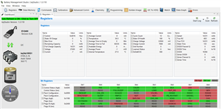
I have been working on BQ34Z100-G1 and having some problem with calibration of voltage and current.
How i am doing the experiment:
- soldered a brand new IC on my custom PCB.
- calibration is working perfectly fine with bqstudio and EV2400 module.
- Now I am connecting a load of 3A to do the current calibration, this time i am having problem with calibration, bqstudio says: "calibration - Failed to enter calibration mode with command 0x2D".
- Just to find out the problem, I changed the BQ34Z100-G1 and performed the same experiment after removing the 3A load. This time calibration works.
- I am able to communicate(I2C) with BQ34Z100-G1, even in the case when calibration does not work.
I am using a battery powered supply of 24V and checked voltages at
- Vreg = 2.5v
- Vbat = 0.9v
- Vce = 3.3v
- Vregin = 3.3v
- Ven = turns on/off at a certain frequency to enable the voltage divider circuit.
I don't know what goes wrong after adding the load that does not let the IC work properly.
Edit:
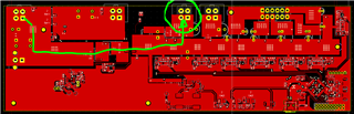
I have old version of PCB layout design that works fine even when i apply the load. So i thought i have some problem in my new PCB layout design and I am sharing this new design for your reference.
Green circled connector is where is the 3A load is applied and the green doodled line represents the power flow path.
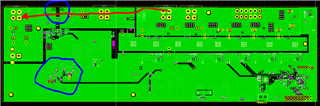
Blue circled areas have sense resistor and BQ34Z100-G1 IC. Red doodled line represents the GND return path. Return current has to pass through a MOSFET switch and sense resistor.
Please help.
Thanks.