This thread has been locked.

If you have a related question, please click the "Ask a related question" button in the top right corner. The newly created question will be automatically linked to this question.

TPS65987D: PD role swapping not working

Part Number: TPS65987D
Other Parts Discussed in Thread: BQ25792, TPS65987

Hi,

I'm having some trouble getting power role swapping to work. I've tested with an LG and a Samsung device and neither are able to successfully role swap.

The Setup

I am using a TPS65987D alongside a BQ25792. The system is intended to be a dual-role PD device with a sink role preference. The TPS is connected to the BQ via its I2C3 master port. When operating as a sink, it configures IINDPM in accordance with the negotiated contract event and enables charging. In source mode, it configures VOTG, disables charging and enables the OTG bit. IOTG is 3A for all contracts.

The Problem

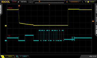
I can see the correct register writes taking place on I2C3 after the FRS event is triggered from the phone. However the role swap never completes. Below are a CSV dump of the CC line activity, as well as the voltage waveforms for VBUS, PP_HV, and CC.

PR_SWAP Fail.csv 

VBUS in the context of CC

VBUS in the context of PP_HV (common net between the TPS65987D and BQ25792's VAC1/2/VBUS, which are all shorted on this design).

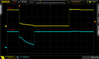
To my untrained eye, it looks like the TPS65987 switches are taking too long to close. PP_HV is ready relatively quickly - that is the BQ25792 bridge direction reverses to be a source. However 5V doesn't appear on VBUS again until over 1 second later. Looking at it closely it looks like what the eventual rising edge on VBUS corresponds to, is actually the phone reverting back to being a source. That's the only thing that explains why there's a slight sharp jump in voltage on PP_HV shortly after the rising edge on VBUS.


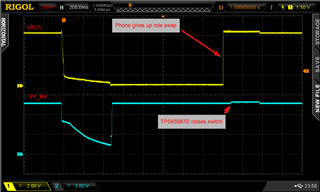
So the question is, why is the TPS not closing the switch shortly after the rising edge on PP_HV? It's clear the FRS even is being properly generated. Otherwise you wouldn't see PP_HV rise at all, which corresponds to the BQ25792 being told to switch into OTG mode via I2C.

I've attached my project file, which contains all of the config, as well as the I2C commands sent to the BQ25792 on various event triggers.

TPS65987D_DRP_FRS.pjt


  • Hi Arda,

    I would need some time to look through this issue. Can you provide PD logs?

    Regards,

    Raymond Lin

  • Hi Raymond,

    Thanks. Yes they are here.

    Unfortunately I don't have the budget for a TotalPhase setup so I make do with the small Cypress protocol analyser. You can open the file directly in the EZ-PD software to decode it as described here:

    e2e.ti.com/.../4133929

  • Hi Arda,

    I will take a look at it and let you know by Wednesday. 

    Regards,

    Raymond Lin

  • Thanks mate, appreciate it.

  • Hi Arda, 

    On a side note, did you follow the schematic guidelines when designing your board?

  • Schematic or layout? If you're referring to the section toward the end of the datasheet, then I believe so. The main things covered there is tapped bus routing of the USB data lines for BC1.2 and connecting the drain pads to internal copper layers. If there's something more specific you had in mind, let me know.

    Here's a general overview of the routing.


    You can find a redacted version of the schematic in the other thread here:

    e2e.ti.com/.../4136997

  • Hi Arda,

    I will need more time to decode the PD logs data. From my observation though, the PR swap request was successfully processed but after the role swap, the first contract negotiation attempt failed followed by a success, however I can't see the contents of the negotiation right now. Let me consult with my team and I will get back to you by Friday.

    Regards, 

    Raymond Lin

  • No worries. Also, you can use the EZPD protocol analyser software without the hardware to decode the csv for you. Download is at the bottom of the link below.

    www.infineon.com/.../

  • Thank you for the information, I'll look into it and get back to you by next Tuesday as I'm currently occupied with a lot of other works at the moment. 

    Thanks and Regards, 

    Raymond Lin

  • Hi Arda,

    What kind of LG and Samsung device are you trying to connect to? 

    Regards,

    Raymond Lin

  • Hi Raymond,

    We have been testing with a Samsung Galaxy S10 and as a second data point, an LG V30.

    On the Samsung, on a few tries I was able to get it to switch roles by quickly unplugging/replugging the cable after flipping the switch. However it's very hit and miss and the timing has to be quite precise. Below is a screenshot from the web of the PD role swap switch on Samsung devices.


    This is what leads me to believe the issue is with the VBUS switch closing in time for the phone to see there is a supply present before giving up. By un/replugging, I am able to force the TPS65987D back into source mode, as on an unplug event I've configured it to put the BQ25792 back into OTG mode (The system should appear as a USB host to any non-PD devices that are plugged in, so we always need Safe5V ready to go). When the cable is rapidly reconnected, the 5V source is up and the phone perceives this as a successful role-swap and is happy to resume the source/sink capabilities negotiation and subsequently pull current.

    In the OP I said "The system is intended to be a dual-role PD device with a sink role preference." To add a little more context around this, the TPS lives in a battery powered system which has USB host and device capabilities. As mentioned above it needs to appear as a host to devices like USB hubs or flash drives. This is the reason for the port to rest in the OTG/Safe5V source state when disconnected.

    When a PD-capable device is plugged in, the system should prefer the PD sink role, as the primary use case is that it is plugged into a USB PD wall charger. However it should also have the option to act as a PD source if a role-swap is requested, allowing it to be used as a small power bank.

    Hope this makes sense, and adds some clarity as to why the project file and the I2C Master events are configured the way they are.

  • Hi Arda,

    There has been many cases with Samsung devices not compatible with our PD controllers because of mismatch in compliance. Let me check with my team to see if this is applicable for the Galaxy S10. Have you tried connecting the PD controller to other devices or a tester (i.e. Lecroy, Ellisys, GRL)?

    Regards,

    Raymond

  • Thanks Raymond. That's really helpful feedback. Unfortunately I don't have access to a proper compliance tester and have only these two devices in my possession which are PD capable.

    Regardless, if we're going to offer the 'power bank' feature, it should be able to charge any connected device. i.e. We'd need to make it work with Samsung devices irrespective of compliance mismatch - it's just what an end user would expect.

    With this in mind, I tried changing configuration to Try.Src and also flipped "Initiate swap to sink" to "Initiate swap to source". This way the TPS would default to a source when connected to any sink or dual-role devices, while still be able to accept power from source only PD devices (like power bricks).


    The phone now sinks power on connection, which is good. The role swap however (somewhat expectedly) still fails similarly.

    With sink preferred, there is of course a potential issue with cases where this device is connected to either another power bank, or more importantly a USB-C + PD equipped laptop or PC. The former is more of an edge case, however the latter is a case we frequently expect as the device (in addition to being a USB host) is also configured via USB 2.0. Thus, we don't want it to try to charge the laptop when connected (hence the 'sink preferred' configuration I had in the original project). The laptop/PC should see it as sink/peripheral when connected.

  • Hi Arda,

    Can you record the PD logs between the 987D and the Samsung/LG device? 

    Regards,

    Raymond Lin

  • Hi Raymond,

    The log file in the OP named PR_SWAP Fail.csv is between the 987D and the S10.

  • Hi Arda,

    I checked with my team and seems like there has been numerous cases with Samsung devices not working with our PD controllers. I would need to look more into your case to see it's similar to those issues as well. I'll get back to you next week. Thank you for your patience.

    Regards,

    Raymond Lin

  • Thanks Raymond. Appreciate it. Also feel free to reach out to me directly via email as well. We can set up an NDA and perhaps go through our system in-person with a bit more detail than I can discuss on a public forum.

  • Hi Arda,

    Do you know the source/sink PDOs for the Galaxy S10? From the PD logs, my guess is there might be a mismatch in what each device (PD and S10) can sink and offer. 

  • Unfortunately the S10 doesn't seem to advertise its sink capabilities (my understanding of the spec is that it's optional). However I did another test which yielded interesting results, so this is a fortuitous thread you've pulled on...

    Plugging the S10 into a COTS power bank or power brick, it always seems to choose the 9V PDO. However plugging it into my board (which is running the Try.Src config from 6 posts ago), it chooses the 5V PDO (as an aside, the BQ25792 seems to be regulating rather poorly in reverse under load but this is a separate discussion). This is interesting because my board offers all of the common source PDOs at 3A. You can verify this in my prj file. The S10 chooses the default (5V) PDO.

    I also tested these Source PDOs work with the Duo Sink board. Plugging it in and cycling through the 5, 9, 15, 20V buttons produces a corresponding output voltage change on my board.

    Another test I did was to plug the S10 into a Duo Source which is loaded with the demo firmware and on which I have pressed all the buttons to enable all the PDOs. With this, the S10 picks the 9V PDO as it should. So I suspect something's wrong with my project's configuration that doesn't allow the S10 to access the other PDOs I'm offering and perhaps, this also influences the role swap issue?

    To answer your other question, the S10 only offers 5V @ 500mA in its Source Capabilities advertisement.

  • Hi Arda,

    I'll look into this with my team and get back to you. 

    Regards,

    Raymond Lin