I would like to know about transtition of AC and Battery.
If you can, could you reply as soon, please?
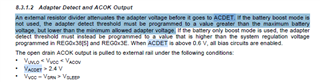
1. About ACFET/RBFET OFF condition.
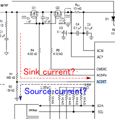
When AC adapter is removed, if battery voltage maximum is higher than ACDET setting,
Is ACFET/RBFET not OFF eternally?(until battery voltage goes down by self discharge etc.)
Or, charger detects the reverse current by ACN/ACP, then Charger stops ACFET/EBFET? Which is correct?
Or if other behavior is correct, please teach the it, please?
We are worrying that if ACDET setting is lower than battery maximum voltage, ACFET/RBFET does not OFF when power supply is Battery only?
2. When Hybrid boost mode, if AC adapter is removed, Battery boost will be stopped by ACP/ACN current is lower than Hybrid Power Boost Mode Exit threshold (IDPM_FALL)? Is it correct?
3. Is Hybrid Power Boost Mode Exit threshold(IDPM_FALL) 93%/96% of ILIM1 set in REG0x3F()?
Or based on other REG of 93%/96%? Please teach me.
4. When Battery charging in Buck mode, if AC adapter is removed and in case that ACDET setting is lower than battery voltage, will charging not stopped?
Or will be stopped Battery charging by anything behavior?
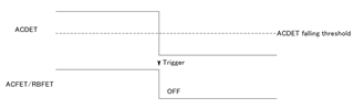
5. When AC adapter is removed and ACDET is low then ACFET/RBFET is OFF, before ACOK condtion, Power supply is from battery via BATFET body diode?
If ACDET is low but ACOK condition is not valid, Power supply is from BATFET's body diode continue until ACOK condition is valid?
Best regards,