Other Parts Discussed in Thread: TPS54160
Hi, TI Support Team
My BUCKEVM is broken and experiencing the following problem.
1.For unknown reason the output capacitor C16 was broken down, and the test resistance size was 2 ohm, while the C17 seems to be fine (the test resistor are extremely high).
2.Then we try to debug and find out what's going on for this EVM, so we short J16,J23,J24, which means that we have selected another set of capacitors and the corresponding compensation parameters. In this situation, if in this EVM only output capacitor C16 is broken, the EVM should work properly when OP J17 and short J16,J23,J24. However, we find that when the power supply is connected and the load is open, the converter has no constant voltage effect. Experiments show low-frequency sawtooth waves at output voltage, which is a very abnormal phenomenon. With the Input voltage rises, the frequency of output voltage waveforms rises.
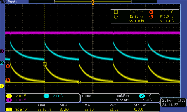
3.In experiments, the load is off. When Vin=3.5V, Uo_max=3.72V and Uo_min=0.64V, fs=5Hz, as FIG.1. When Vin=6V, Uo_max=6.3V and Uo_min=3.12V, fs=30Hz, as FIG.2. When Vin=8.5V, Uo_max=9V and Uo_min=5.6V,fs=80Hz, as FIG.3.
4.In measurement, when using the multimeter to measure the value of R8, in the broken EVM the value is 131 ohm while in the other new EVM it should be nearly 8K ohm (The nominal value of resistance R8 should be 10K). So we took resistance R8 off and break the inductive loop at the same time, and measured the resistance from TP19 to ground, which is 134 ohms. It means that the resistance measured from the Vsense pin of the chip was 134 ohms. From the manual chip manual, it can be seen that Vsense is an internally-run inverted input, and the value measured on a normal chip should be a very large number, so we consider if the chip has been damaged and I would like to know how to test whether the IC chip TPS54160 is damaged or not.
The corresponding experimental waveform is shown below, where CH1 Uo, CH2 Vcomp(TP17), CH3 Vnode(TP9).
I would like to know what the EVM probably is malfunctioning and why it is causing this failure, because according to the EVM design the output capacitor should not break down (in the experiment the input is between 3.5-30V, the output voltage is fixed at 3.3V and the capacitor withstand voltage is 10V).
In addition, I would like to try to fix this EVM board and locate the corresponding error. It is currently determined that C16 is damaged, the IC chip TPS54160 may be damaged, the C17, internal MOSFET nor the external regulator tube is fine (compared with another new EVM).
What's more, in our experiment, the Vin is from 3.5-30V and the load is from 0.15-2A, which is within the reasonable range. Can you tell us what possible reasons may cause to the damage to this EVM so that the next time we can pay attention to it to protect our EVM.
Thanks for your support!
Best regards.
Fig.1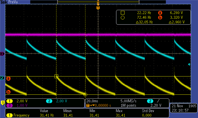
Fig.2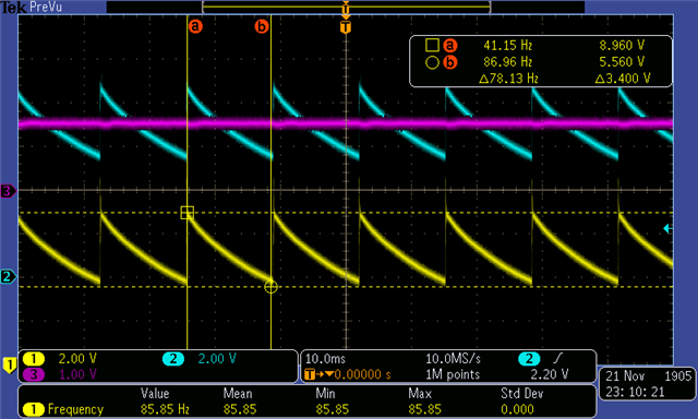
FIG.3