This thread has been locked.

If you have a related question, please click the "Ask a related question" button in the top right corner. The newly created question will be automatically linked to this question.

BQ25700A: SMBus ADC value reading Zero for all reads even after enabling ADC option

Part Number: BQ25700A

Hi

BQ25700A registers are read in below two cases .

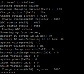
Case 1 : By powering the IC from external battery (4S battery) without connecting external power source

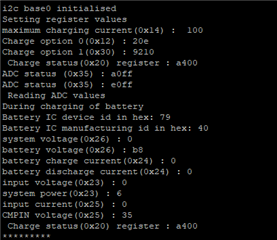
Case 2 : By powering the IC from external power source (12V input with 0.5A limit) without connecting battery.

But in both cases i'm observing same output.

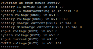
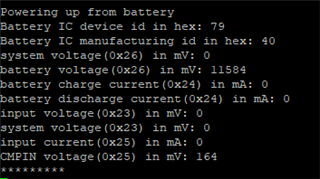
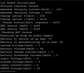
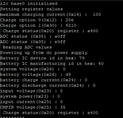
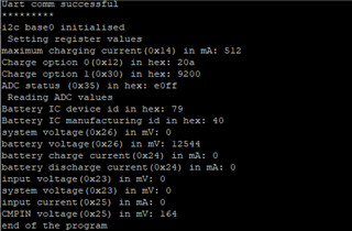
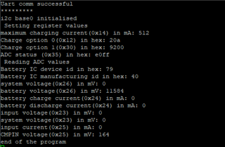
Please find the register values read in screen shot below. ADC reading all are showing ZERO. In case of battery voltage read, the voltage is not stable (register values read in two adjacent reads shown below).

Battery register values read first time

Battery register values read second time

Please advice how to fix this issue.

  • Hello Bivin,

    Based on ADCOption() setting of 0xE0FF it looks like you are enabling continuous conversion and all ADCs enabled. Please try to break this out into two steps to set up the ADCOption register and then start the ADC. i.e. ADCOption -> 0x60FF , then ADCOption -> 0xE0FF.

    Also, try to loop the measurement in your code as the ADC will update every 1s in continuous mode.

    Without seeing your code or schematic I can't say why you're not seeing a repeatable measurement on VBAT. Please try the above steps.

    Thanks,
    Khalid

  • Hi Khalid

    I tried the suggested ADC register option in the sequence you mentioned, but it is still not working.

    Can you provide the register setting sequence which need to be followed in a typical scenario.

    Regarding schematic, you may refer the related post of this query. But since i'm able to read Device & Manufacturer ID, i think schematic is proper, anyway please have a look at the schematic.

    Can you clarify whether the battery IC is having a volatile or non-voltage memory. Will this affect coding.

    Please note that IC is operated either from direct power supply or from battery and not both together.

    Please reply.

    Regards,

    Bivin

  • Hello Bivin,

    Since you are reading something in register 0x26 for battery voltage, then the ADC should be getting enabled correctly. I was reviewing your outputs more closely and I see, for example, System Voltage (0x26) = 0mV. However, the full range of this ADC is 2.88V to 19.2V so please check your calculation in your script. You can share the actual register dump if it helps. Out of the rest of the ADCs, I would expect ICHG and IDCHG to be 0 as the LSB is very large on these, VBUS should be 0 when powering from BAT, and if you are not using the PSYS feature then this would also be 0. The only one that does not make sense to me is the System voltage (0x26) which should not be 0.

    The device's registers are all volatile, upon POR you need to reset the registers. The device can be operated from VBUS or from BAT, in BAT mode you need to disable Low Power mode to use the ADC.

    Thanks,
    Khalid

  • Hi Khalid

    System voltage is showing zero in HEX value also.

    Please advice.

    Regards

    Bivin

  • Bivin,

    I would recommend to focus on power up from VBUS and get the ADC working as expected. This will be simpler than power up from Battery only. Please confirm the VSYS voltage manually as well and confirm all your register reads/writes are working properly.

    Thanks,
    Khalid

  • Hi Khaild

    I tried reading multiple registers and tried different register read/write sequences, but still I'm having issues in reading ADC registers. Also, i'm not sure whether there is any issue with circuit. Please review the schematic implemented in link below.

    https://e2e.ti.com/support/power-management-group/power-management/f/power-management-forum/1115101/bq25700a-review-on-the-circuit-implemented-using-bq25700a-in-boost-mode

    The values read by powering the circuit from external source of 12V is shown below.

    The values read by powering the circuit from 4S configured battery source (14.8V) is shown below.

    The values  read are incorrect.

    I have maintained all require wait timings.

    Please let me know how to trouble shoot this, is there any register read write sequence to be followed.

    Regards,

    Bivin

  • HI, Bivin,

    To use ADC measurement, first enable the ADC channels, then send a command to ADC_START by writing '1" to REG 0X35 bit 13. 

  • Hi

    I tried the above settings but still  getting same results as above.

    Suggest how to check the register settings are proper or not .

  • Hello Bivin,

    Can you try with TI EVM software (Battery Management Studio) to rule out any issue with your code?

    I will take a look at your schematic and let you know if I find any issue.

    Thanks,

    Khalid

  • can you share step by step register read and writes required for reading ADC values.

    I'm able to read device ID as shown in previous mail.

    But ADC values are not read.

    Please let me know if any hardware checks or voltage checks to be done to solve this issue.

    Please reply.

  • The power-up sequence from DC source is as follows:
    1. 50 ms after VBUS above VVBUS_CONVEN, enable 6 V LDO and CHRG_OK goes HIGH
    2. Input voltage and current limit setup 
    3. Battery CELL configuration
    4. 150 ms after VBUS above VVBUS_CONVEN, converter powers up.

    The above steps are performed by the device on power-up. After this point, please confirm CHRG_OK pin is high, REGN = 6V, and ChargerStatus(0x20) has no faults.

    After this, you can set 0x35 to 20FF or A0FF to select the ADCs, then enable the ADC by setting Bit 14 of the same register to 1. (0x60FF or 0xE0FF).

    As mentioned previously, some of those ADCs will read 0. You should see non-zero values for VBUS, VSYS, VBAT.

    Thanks,

    Khalid

  • Hi

    Sch link is below.

    https://e2e.ti.com/support/power-management-group/power-management/f/power-management-forum/1115101/bq25700a-review-on-the-circuit-implemented-using-bq25700a-in-boost-mode

    Observations while testing the battery IC are as follows:

    Powering with power supply: voltage at EP3 went to 16.6V for some time and came back to 12V. Register values read is attached below.

    Powering with battery: voltage at EP3 is 14.5V

    With both supply and battery ON: voltage at EP3 was 14.7V with increase in current of about 10-20 mA.

    All the register values in the below image are hex values without any conversion to eliminate any errors during conversion.

    ADC values read are not proper.

    Please advice on how to fix this issue.

  • Bivin,

    Can you share your code? In your attachment there is a comment "Powering up from dc power supply" after the initial setup. Are you doing a reset there? that would clear settings that were put in registers prior to that line.

    Khalid

  • Hi Khalid

    Powering up from dc power supply is only just printing a text.

    Please comment on the screenshot shared, let me know whether any register read is incorrect or not, values are in hex format.

  • Hello Bivin,

    The register settings and sequence look OK. The ADC reads ~12V on VBAT (which matches what you see manually on EP3) but 0 on VSYS. BATFET should be closed so you should see roughly the same voltage on VBAT and VSYS. Can you measure directly on EP2 to see if you see 12V there as well?

    I reviewed your schematic again and I don't see any issues there.

    Note that the default settings for 4S are MinSysVoltage of 12.288V and MaxChargeVoltage 16.8V. Without a battery present it should regulate just above MinSysVoltage (~12.4V is what I see on my setup). You mentioned you see VBAT start out around 16.6V and then drop to 12V.

    Please check CHRG_OK voltage as well as REGN voltage, VSYS (at EP2 on your schematic). You can also change the MinSysVoltage (0x3E register) to see if it changes the voltage at EP2/EP3 as well as the ADC reading. 

    My suspicion is there could be some kind of hardware fault, so please check for any short between VBUS and VSYS side.

    Thanks,

    Khalid

  • Hi Khalid

    Please find our observations below.

    Testing observations are as follows

    CHR_OK = 3.3V, REGN = 6V

    1. Power on with supply

    VBUS = 12V, VSYS = 16.8V, VBAT = 16.8V (on oscilloscope)

    Charger status showing fast charging mode

    2. Power on with battery

    VSYS = 14.5V,  VBAT = 14.5V (on oscilloscope)

    3. While charging of battery

    VBUS = 12V VSYS = 14.6V,  VBAT = 14.6V, more current drawn indicating that battery is charging

    Charger status showing fast charging mode

     Non zero value of system power is observed

    There is no short between Vsys & Vbus. All voltages are proper on board (tested using oscilloscope). Vbat is reading properly (values in different mode is different which is similar w.r.t board values).

    But ADC reading for Vbus & Vsys are always zero.

    Please suggest how to debug.

  • Hello Bivin,

    Thanks for this latest information. I have reached out via email to help debug further.

    Thanks,

    Khalid