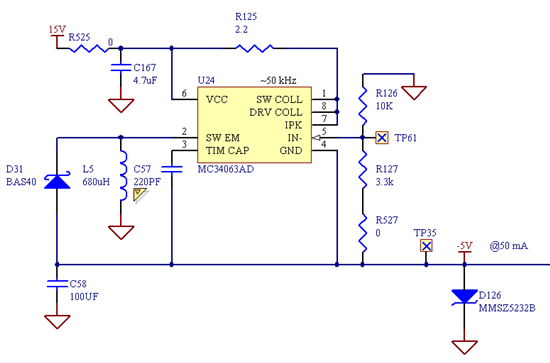
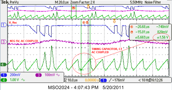
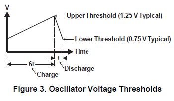
Hi all, I have a working inverting regulator using the MC34063 configured as shown in Figure10 of the TI datasheet. External timing capacitor Ct should ideally charge and discharge between 0.75 and 1.25 V thresholds, yielding a voltage delta of 0.5V but I'm seeing it discharge all the way to 0V which gives a voltage delta of ~1.25V. Has anyone else seen this behavior? *the chip is actually an OnSemi variant, my apologies in advance*
My design specs are below. Component values is in agreement with those given by the nomad design tool.
Vin = well regulated +15VDC.
Vout = -5VDC
Iout = 50mA
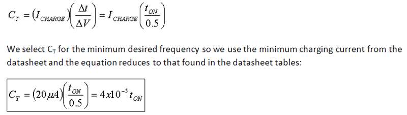
Fsw = 50kHz