This thread has been locked.

If you have a related question, please click the "Ask a related question" button in the top right corner. The newly created question will be automatically linked to this question.

LMR62014: Issues with Overcurrent / Short Circuit Protection (slva998a.pdf application note)

Part Number: LMR62014


Hello,

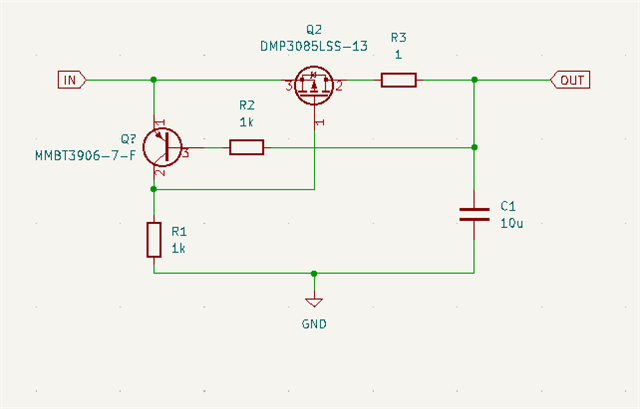
We are encountering an issue with the short circuit protection design from the slva998a.pdf application. We have implemented Figure 4.4 in the application. We have also adjusted the issue that the reference design had.

(please refer to this previous Forum Post: https://e2e.ti.com/support/power-management-group/power-management/f/power-management-forum/1086812/lmr62014-overcurrent-short-circuit-protection-for-boost-converter?tisearch=e2e-sitesearch&keymatch=slva998a.pdf#)

Below is the circuit we are using. The Rsense we have selected is 1ohm. This is just an initial value to confirm if the circuit is working. From computation we are expecting around 0.67A threshold current. 

Here are the issues we are seeing, we are connecting a power supply in the input at 12V 1A limit. 

The load that will be eventually connected to the output is a 12V FAN with the current draw of 300-350mA. 

The initial setup we did to test the circuit was to test it with an electronic load set to CC mode at 350mA current. 

The setup only works in a particular order of events in testing.

1. Connect Power Supply Cables to Input of circuit protection

2. Connect Electronic Load cables to Output of circuit

3. Turn ON power supply. Electronic Load CC mode is still OFF but the meter is reading the correct voltage.

4. Turn ON Electronic Load and the load is drawing the set 350mA current. 

We also increased the current draw until we see the threshold. When electronic load CC mode current goes to 670mA, the output becomes 0V. Then it only goes back to 12V when we turn OFF the Load. The only issue is that it does NOT work if the electronic load is already ON. before turning ON the power supply. 

We also connected an actual Load (FAN and resistors). The resistors were chosen so that it would draw similar current. 

For both scenarios the FAN does not turn ON and the resistors do not draw the correct current when you connect it to the protection circuit then turn ON the 12V. The voltage measured in the FAN side is around 2V. The FAN also does not turn ON even if you connect the and turn ON the 12V first. 

We then tried connecting a lighted load to the protection circuit (330ohms)

We tried both methods: connect load first then turn ON 12V and turn ON 12V then connect the load. 

Connecting the supply first then load shows the correct current draw from the supply and voltage across the 330ohm resistor. 

Connecting the load first then turning ON the supply shows 6V across the 330ohm resistor. 

What might be the cause of these issues? Are there specific values that I need to use for the other components. Are there limitations with the having a lower current protection threshold not indicated in the application note. Does the values/type of load we connect to the current protection circuit affect its behavior? 

Thanks,

Deniel

  • Hi Deniel,

    Thanks for reaching out. For your questions, this is the feature of the protection circuit. When you connect to the load first, and then turn on the power supply, it works like this:

    First, Vin is 12V but Vout is still 0V because it needs time to charger output capacitor C1, so in this time the BJT Q? is conducted.

    Then, it will charger C1 with base current of BJT, maybe several mA, it depends on the spec of BJT you use. At the same time, if you have a load parallel with C1, C1 will also discharge from the load. So it can't establish a right output voltage.

    You may decrease the value of R2 to decrease the charge time of C1.

    Best Regards,

    Nathan Ding

  • Hello Nathan,

    Thank you for the explanation of the protection circuit.

    I decreased the value of R2 from 1k to 220ohm. The Issue still exist with the load connected before powering ON but I am now able to turn ON a fan that has much less current current draw (50mA) but the output still drops to ~4V. I am still not able to turn ON the 330mA fan that I am intending to use. Does this mean I still need to decrease R2 to decrease the C1 Charge time. 

    What should be the ratio between the leakage current (Ib) of Q?  and the current that my load sinks? Should The leakage current be greater or near the 330mA that my load draws so that it can establish the correct voltage? I am currently MMBT3906 PNP Transistor (The PNP counter part of the MMBT3904 in the application note). My R2 can't get lower than 220 since it would be nearing the maximum base current of the transistor.

    Will lowering the value of C1 also help with the parallel load? Or is it the combination of the leakage current from Q? and output capacitor that would resolve this issue? 

    Does using a FAN (inductive load?) also play into account the behavior of the protection circuit startup phase?

    Thanks,

    Deniel

  • Hi Deniel,

    Thanks for replying.

    Yes, if it still can't turn on 330mA FAN, it means the charging current is not large enough or your load is too heavy. This circuit can't start up with too heavy load. You can replace BJT with the one with higher base current limit, if not, I think maybe you should change your solutions.

    Lowering the value of C1 can't help with this because it will also change discharge current through the load.

    Inductive load may have impact in transient state but will not infect the final value of output voltage in steady state.

    Best Regards,

    Nathan Ding