This thread has been locked.

If you have a related question, please click the "Ask a related question" button in the top right corner. The newly created question will be automatically linked to this question.

solar charger

Other Parts Discussed in Thread: BQ24071, TPS61200, TPS63010, BQ24030, TPS61220, TPS61070, TLV431, TPS61170, PMP, BQ24450, BQ24650, TINA-TI, TPS61020

Hi

For a solar charger solution, I am looking at 2 possible implementations;

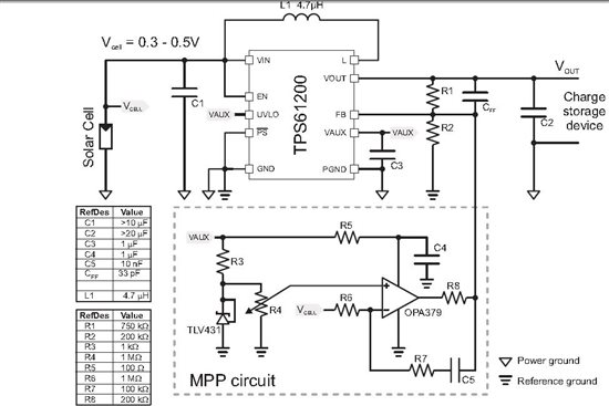
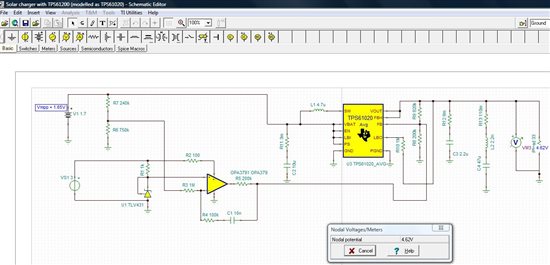
  1. previously discussed on this forum (and in app note slva345a), a design based on a 3 cell panel with TPS61200 + MPPT ---> bq24071 Li ion charger ----> TPS63010.  The charger has a 3 cell PV panel with 1.5V vmpp and up to 500mA at Vmpp.  The TPS61200 dc converts this and provides Vin for the bq24071 to charge a built in Li ion cell.  The TPS63010 then dc converts the battery voltage to 5V. 
  2. TI present a design in Nigel Smith's/Jinrong Qian's app note using bq24030  (slua394).  I realise that I need a higher voltage panel to drive the bq24030.  but I am considering prototyping and following the bq24030 with a dc conversion stage.

Which approach is more likely to be the 'best'?   Criteria are electrical efficiency and BoM cost.  I have EVMs for option 1 above. 


Tks

Tony

  • The bq24030 solution is more integrated than the TPS61200 solution.  This makes it easier to design, smaller, and likely cheaper.  The main drawback is that your panel must have a voltage above the battery voltage for any charging.  When you design for this case, you will likely typically have a much higher panel voltage which means more panels in series which costs more.

    The TPS61200 allows charging with nearly any light condition--down to 0.3V for the panel.  However, there is an extra boost stage at the front end which has average efficiency at the lower panel voltages.  But you are charging at these lower light conditions, whereas with just the bq24030, you may not be charging in low light.

    So, the bq24030 is more efficient at converting light to energy, but cannot charge in all light conditions unless you have enough panels in series to generate a voltage above your Vdppm.  However, the bq24030 requires more panels which adds to the cost compared with the extra ICs in the TPS61200 approach.

    For the conversion from the battery to 5V, you just need a boost, not a buck-boost.  You can look at the TPS61070 or TPS61220 for this, depending on how much power you need.

  • Hi Chris,


    Thanks for the reply.  I may be constrained to use a 3 cell panel (awaiting supplier pricing info), in which case I guess I'll need the TPS61200 solution. 

    For the 5v DC stage, I reckon I'll stay with the TPS63010 for now - I have an EVM and efficiency in boost mode, i.e. range of battery voltage, (from a low of 3V thru  3.7V for the most part up to 4.2V when fully charged) is ok.  As I see it, with power save mode disabled, I get efficiency >=80% or so for load currents in the 50-300mA range.  I'm not sure yet if I'll use power save mode.

    Tony

  • Yes, if 50 mA is your minimum load, power save mode won't gain you much efficiency.

    You could also use another TPS61200 to generate the 5V rail in order to have one less part number on the BOM.

  • Hi

    I am proceeding with the TPS61200 based design with the MPP regulation stage as described in SLVA345A ("Supplying TPS61200 with a single solar cell"). 

    In a previous thread here (April 2010), there was a discussion relating to modifying the MPP circuit to cater for a different PV module voltage (3V). 

    In my case, I have a 3 cell PV module, with Vmpp approximately equal to 1.65V. 

    Referring to SLVA345A schematic, I will add a potential divider at Vcell, which will divide down the Vmpp of 1.65V to 1.24V (same as TLV431 reference).  I connect the divided down voltage to R6 on inverting op amp input.  I can omit R4 and connect TLV431 directly to non-inverting op amp input. 

    Last year's discussion here confuses me, so I'd like to ask my questions. 

    As with the previous poster (almost_linear), I intend to use the bq24071 charge controller, and intend driving this with 4.5V or thereabouts.  So for the TPS61200 above, R1 and R2 would normally be calculated (from datasheet) as R1=R2(Vo/ Vfb -1).  Vfb =0.5V, Vo=4.5V, then R1=8R2.  Setting (for now) R2 at 200k as recommended in datasheet to ensure 1uA of current, then R1 needs to be 1.6M. 

    BUT.... what effect on the R1/R2 divider do the op amp components have?    R8 is recommended to be 200k in diagram table above. Does this appear in parallel with R2 or not? (if it is in parallel, then it affects the voltage setting resistor divider).

    In general terms, can someone explain the basis for the chosen value of R8 in particular, but also R7 (and I guess R6). 

    Do R7 and C5 just allow a slow ramp up to Vaux according to their RC time constant?

    I do have eval boards, and  I intend building a prototype  this week, but I'd like to understand the component choices as I do so.


    Thanks

    Tony

  • I think you first need to understand how the op amp circuit allows operation at the MPPT.  It does this by feeding a current onto the FB pin which tells the TPS61200 to regulate to a lower output voltage.  This lower output voltage is less output power which is less input power which is less current drawn from the solar cell which allows its voltage to rise.  It will add current to the FB pin if its positive input is higher than its negative input.  This corresponds to a panel voltage that is lower than desired, so it will reduce the output voltage to increase this voltage.

    You can do a KCL on the FB node to see how the R1, R2, and R8 values affect your Vout.  The op amp output voltage varies between ground and Vaux.  You cannot just use the datasheet equation as Vout will vary based on how much light you have.  Make sure to keep the maximum Vout (corresponding to R8 tied to ground) less than the 7V maximum rating for the pin.

    You can simulate the circuit in TINA to find the optimal values for your application.

    Thank you for searching the forum to find other discussions on this topic.

  • Hi Chris

    I am designing a circuit which has to do the same thing, I would like it to work under low light but my issue is that I need 7.45V to charge my batteries which are 3 cell SLA. What part would replace TPS61200 ?

    Thanks


  • The neat thing about the TPS61200 is that is has a separate low current Vaux supply that is operational before the main supply turns on.  This allows it to power an op amp before the switches turn on.  Thus, it limits the output voltage before it is up and running and limits the inrush and droop of the panel.

    This same thing can be accomplished with 2 separate ICs to do these 2 tasks.  So, a charge pump to power the op amp and a boost to take the panel voltage and power your charger.  The TPS61170 could be your boost.  What is your panel's output voltage range?

  • Solar panel is Voc 10.8V and Vmp 8.8 Pmp 5W.


  • So, you would need a buck solution then.

    Since your panel voltage is so close to your battery needs, why not just put the panel straight into the bq24450? 

  • I just reread your other thread.  The bq24650 would also work and would regulate at the MPPT.  The bq24450 is simpler, being a linear charger.  It would pull as much current as it could from the panel, limited only by its dropout or the maximum charge current that you program.  Thus, it would always operate in dropout which is efficient for a linear solution.

  • Hi Chris

    The only question I have using a higher voltage is how it will behave under low light ? That is why I had chosen a lower voltage previous but since my battery is higher than 5.5V (TPS61200 Vmax) I had no choice, I am about to get a prototype done and see how this will work under low light. One of the advantage that everybody is talking about using TPS61200 is the boost capability under low light. I will get this done and post back once I have my data.

    Thanks


  • For Tony,

    R6 and R7 set a gain of the op amp while C5 is used to slow it down and keep it stable.  I suggest that you start your circuit with these values and then tweak them if needed.

  • Hi Chris


    Thanks for the advice, I spent last night learning and modelling in TINA-TI.  It's a nice tool and I've managed to learn enough about its capabilities to allow me to understand more how the TPS61200 MPP regulator operates. 

    In the absence of a macro model for the TPS61200, I've used the model for the TPS61020 which I think is largely similar bar missing the Vaux capability. 


    I've just shown the 3 cell PV panel as a voltage source which I directly edit to change its output voltage (above and below specified Vmpp of 1.65V).  The potential divider is 240k and 750k, giving 1.25V to the op amp with Vpanel = 1.65V.  Vopamp output then is close to 0V (196uV).  TPS61020 Vout is 4.62V which is fine.  Vfb resistors are 820k and 200k.

    If I increase PV panel voltage to say 1.9V, everything stays the same, so I think this is ok.  Proabably moving off MPP curve, but current delivery should be maintained.

    If I decrease PV panel voltage to say 1.4V, then opamp output swings to Vaux (which I've just set at 3V in my model).  Voltage at FB pin of TPS61020 now goes to 1.5V and Vout becomes 1.4V.   This is desired behaviour I guess, output power will decrease, thereby decreasing input power and thereby current, allowing panel to float back up to MPP voltage. 

    Preparing real prototype now based on above componet values.

    Tony