Hi:
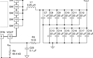
Why we should place a 10 ohm resistor with a 0.1 uF capcitor from the output to the VOUT Pin? Can I change the RC value to 1 ohm and 0.01 uF?

Thanks!
Jiajun


This thread has been locked.
If you have a related question, please click the "Ask a related question" button in the top right corner. The newly created question will be automatically linked to this question.
Hi:
Why we should place a 10 ohm resistor with a 0.1 uF capcitor from the output to the VOUT Pin? Can I change the RC value to 1 ohm and 0.01 uF?

Thanks!
Jiajun


Hello,
The control is based on D-CAP+ mode adaptive time and the ON-time is function of input and output voltage. The cycle begins when the current feedback reaches an error voltage level which is the amplified difference between the reference voltage and the feedback voltage. The VOUT pin should be clean and the noise should not be amplified. The RC is to decouple the switching noise. 10 Ohms and 0.1 uF introduce a 1us time constant. In frequency domain, it is a low pass filter of 159KHz and this is at least 3 times below the lowest switching frequency 600KHz. The RC filter of 10 Ohms and 0.1 uF is recommended because it is optimized and verified on test.
Is there any reason you want to change the RC to different values?
Please close this thread as resolved if it answer your question.
Regards
Hello,
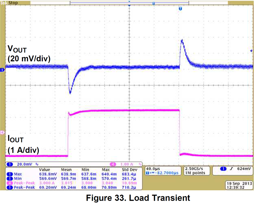
I have a problem that the output transient response is a little bad, so I want to minish the RC value.
Your load transient response is right and similar to the EVM data with bandwidth of 85KHz.

Reducing the RC will not make a major difference. If you reduce the RC pole by half, the bandwidth increases by only few KHz.
Regards