


Other Parts Discussed in Thread: TLV62065, TPS62067
Hi,
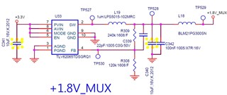
The customer used TPS62067-Q1 to power the video decoder in the instrument cluster.
The schematic has not been modified.
TLV62065 (before) to TPS62067 (after)
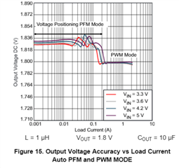
As a result of the review as an issue that appears to be video noise in VIDEO DECODER, it seems that it is automatically changed to PFM mode.
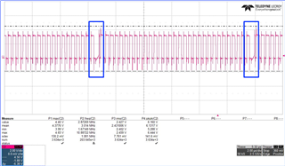
Load current : 450mA
Load conditions require PWM mode operation.
However, the waveform appears to be entering PFM mode.
Refer to the graph, I have to do the PWM operation, but I don't know why it looks like PFM.
Q1. Is the blue area PFM correct? Or what kind of mode is it?
Q2. Please advise if there is any way to improve intermittent PFM.
