Dear team,
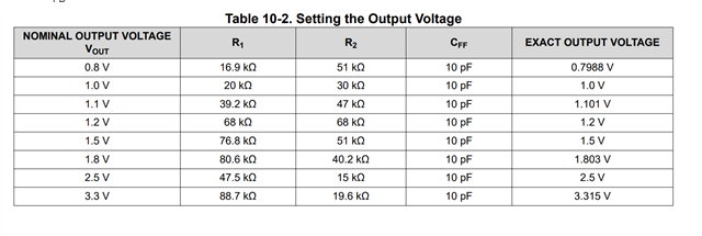
The customer Cff=22pF while we suggest 10uF in the datasheet. The customer wants to know what the risk is?
Thanks & Best Regards,
Sherry
This thread has been locked.
If you have a related question, please click the "Ask a related question" button in the top right corner. The newly created question will be automatically linked to this question.
Dear team,
The customer Cff=22pF while we suggest 10uF in the datasheet. The customer wants to know what the risk is?
Thanks & Best Regards,
Sherry
Hi Sherry,
Thanks for your question.
Do you mean Cff = 22pF instead of 10pF?
I wouldn't expect major changes. The additional zero and pole would also depend on the resistor divider values.
The customer can do a bode plot measurement to check that the application meets their requirements.
Thanks,
Stefano
Hi Stefano,
Could you please tell me what "a body plot measurement" is?
Thanks & Best Regards,
Sherry
Hi Sherry,
Sorry for the typo.
I meant a BODE plot measurement.
For reference: How to Measure the Loop Transfer Function of Power Supplies (Rev. A)
Thanks,
Stefano
Hi Stefano,
Thanks for your help!
Do we have any tool to simulate the Phase margin result? Or do we have any calculation formula for Cff?
Thanks & Best Regards,
Sherry
Hi Sherry,
We have the Simplis model in the product folder (TPS62812-Q1 data sheet, product information and support | TI.com) for the bode plot simulations.
However, I would recommend to directly test it on the customer PCB to get more accurate results.
If you use the resistor divider recommended in the datasheet, a capacitor of 10/22pF should be fine.

If you use very different resistors values (not recommended), you can scale Cff inversely proportional (higher resistance, lower capacitance) as first approximation.
Thanks,
Stefano