This thread has been locked.

If you have a related question, please click the "Ask a related question" button in the top right corner. The newly created question will be automatically linked to this question.

TPS62913: Role of S-CON (Spread Spectrum Modulation) in design

Part Number: TPS62913

Hello ,

What is the recommendation of S-CON pin for noise immune system in TPS62913 regulator?

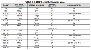
In the data sheet, Table 7-1 (S-CONF Device Configuration Modes) is telling about the device configuration modes.

In my design I am using this regulator in several different places and corresponding the pin has connected to to Vin and Gnd.

1. for 5V nominal input this pin is connected to 5V input.

2. For 12 volt input it is connected to Ground. But for 5V output this pin is connected to 12V input, that is bit confusing to me.

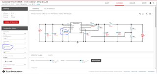
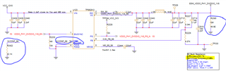
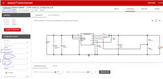
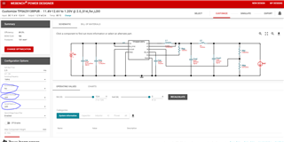
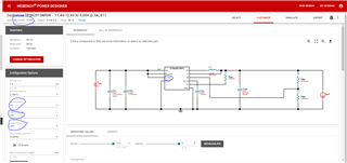
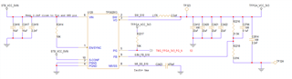
I run the simulation in the web-bench for all rails and created the design accordingly by selecting the pin connections. Sharing some screen-shots for your reference. 

Please suggest the selection of S-CON pin, which will be the best configuration for the noise immune o/p voltage and device?

Your quick reply in this regards will be highly appreciable.

One more query I have related to EN pin. For Hardware enabling, should I connect the EN pin direct to input? Or Should I use Pull-up and Pull-down resistor?

Please suggest.

  • Hi Kapil,

    My colleague Steve will give you response by tomorrow!

    BR

    Zixu

  • Hello, 

    The selection of the S-CONF pin is dependent on your specific design requirements.  You can see the different choices in table 7-1 in the datasheet (shown below for your convenience):

    In most cases, spread spectrum is not needed, so I would start with a setting that has that OFF.  Also, if you are not synchronizing to an external clock, I would choose a value that has No in that column.  That should reduce the options you have to look at.

    The low noise feature is determined by the NR/SS cap, and the default selection should be fine.  For the lowest output ripple at the switching frequency and above, be sure to include the ferrite bead filter option in Webench, which you do not have selected. That will as a ferrite bead in the output path, along with additional caps, which reduce the output ripple by ~30dB. 

    As for the EN, you can use a resistor divider to set a custom EN threshold, or tie directly to your EN source as long as the high is greater than 1.04V.

  • Hello Steve,

    Thanks for the clarification. But there is one more configuration Output Discharge. So for this configuration, the S-CONF resistor value is 18.2K. and  As per the datasheet, I need to keep the 7ohm resistor at the o/p parallel to o/p capacitor. But one of IC BCM Switch recommending the 49.9 ohm resistor. So if I keep 49.9 ohm it means I am increasing discharging time, in that case what will be impact on IC and o/p? Please suggest.

    Should I configure the o/p discharge ? what is your suggestion on this?

  • Hello, 

    The output discharge feature is dependant on your system requirements.  If the BCM device is recommending a bleed resistor to discharge the output during power cycles, then I would recommend that you have the output discharge enabled and not include an external bleed resistor, and you are correct, the output will discharge faster than with an external 49.9ohm resistor.  The feature allows the output to go to 0V even if the load (in this case the BCM device) does not discharge the output caps.

  • Hello Steve, 

    Thank you so much for the clarification. I understood, while enabling the o/p discharge feature, we don't need to keep external bleed resistor. I just need to connect the S-CONF pin with simulated value (22.1K for this case) pull-down resistor right?  

  • That appears to meet your requirements.