This thread has been locked.

If you have a related question, please click the "Ask a related question" button in the top right corner. The newly created question will be automatically linked to this question.

BQ27411-G1: BQ27411 Settings

Part Number: BQ27411-G1
Other Parts Discussed in Thread: BQSTUDIO, EV2400

Hello,

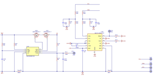
We are using BQ27411-G1C for one of our projects.(We are using a battery with 3200 capacity, 3.7 volt nominal voltage, cut off current of 50 mA) I have questions about a few parameters: 


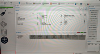
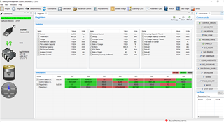
1 - In the IT cfg register I use typical values for all parameters except, user Rate-PWR. I dont understand how to calculate the correct value. I would appreciate if you can help me with this parameter.

2 - For the taper current i choose cut off current(50 mA) as the limit. Is this a right assumption?

3 - For the  "Ra Table Class", do i have to do any operation, or the gauge calculates these values itself? Since this is an handheld device, it is possible that battery would go to 0 V and gauge would lose its calibrations(If there is any). Would this effect, correct SOC calculation when battery starts charging until calibration is recalculated? If so, is there any way to avoid re-calibration everytime gauge is powered-on. (Please note that ROM is not programmed in my device, therefore i have to load register settings manually if power on reset is detected)

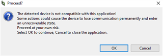
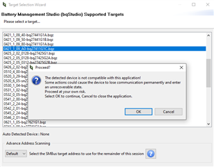
4 - Battery management studio says it does not support BQ27411-G1C. Therefore, i dont know how to program ROM of the device. Is there any way to do it without golden image? 

Thank you,

  • Hi,

    1. Configuring this parameter is not necessary unless your are using Load Mode = 1 (constant power) and Load Select = 6 (user defined rate). With the gauge using its default load mode and load select values, it will track this automatically.

    2. What is the current you are using during normal operation? Typically you want taper current to be around 10% of your normal CC charging.

    3. Ra tracks the impedance of the cell across DOD and will update automatically during discharge cycles.

    4. It is saying that BQStudio is not detecting any device. can you share how you are powering on the device? What connections are being made to what pins? Usually it is okay to proceed past this warning and see if your registers are being read and the device is responding once inside BQStudio.

    Thanks and Best Regards,

    Jackson

  • 1 . Resolved.

    2 . Our device is a handheld mobile device therefore current settings vary wildly during charge & discharge.

    - When device sends data through network it draws around 2A instantaneously, during normal working mode it draws around 70 mA, in idle mode it draws around 8 mA, in ultra low power mode it draws around 0.5 mA. 

    - To charge the device we use USB charger and based on USB type charge current can be 1600 mA(fast charger), 1000 mA(standard charger), 500 mA(USB port). 

    Therefore i cant decide which current to use for calculation. Moreover, even when charging(assume USB charging), if i send data for an instant charge current may go as low as 0 since for an instant modem draws 2A. This is troublesome, therefore i may use some suggestions here to avoid any problem.

    3 . Below you can find our gauge circuit schematics:

    After i connect battery to the circuit, i connect pull up resistors to SCL and SDA(5K ohm) and get pull up voltage from +V output of the device.

    I wake up the BQ29800 since it sleeps before allowing battery voltage to the output. I check the voltages and all seems ok. Then i connect the circuit to the EV2400 as shown below:

    Then i open battery managemnt studio and choose 0421_1_09_A0-bq27411G1C.bqz from gauge list with address scanning set to default. The screen shows nothing, and when i hit refresh button, follow error is shown below;

    To make sure that my SDA and SCL lines connected right, i try switching SDA and SCL cables, wait for 10 seconds, reconnect and restart the Battery management studio. In this case the battery management studio opens up and after a few seconds it closes itself completely. 

    - Then i try setting address to 0xAA rather than default. In this case the screen show something like below, which makes no sense at all and sometimes readings disappear etc..

    Again to make sure that my SDA and SCL lines connected right, i try switching SDA and SCL cables, wait for 10 seconds, reconnect and restart the Battery management studio. In this case battery management studio return an error saying "0xAA returns no answer"....

    - My gauge returns 0xA1 to DM code query when i query via MCU. This code is not documented in the datasheet. Can this be a problem?

    Sorry for the long response but i try to provide as much as i can to help you. 

    Thank you in advance,

    Serdar

  • I have resolved number 3. It seems the connector was plugged into smb rather than i2c. 

  • Hi Serdar,

    Yeah, plugging into Port 1 is a common mistake when trying to communicate with this device.

    In terms of the taper current, 50mA should work fine here. If your current drops during normal CC operation, this shouldn't trigger a valid charge termination. The device is only checking for VCT during CV mode at the end of a charge cycle.

    Thanks,

    Jackson

  • Hi,

    When i open the battery with Battery management studio, i see that some registers are shown wrong and registers are missing. For example:

     - When i check "Res Relax Time" for example, GUI's "Gas Gauging" tab shows it as zero.

    - However when i read the register with Advanced Comm, the setting is right according to the datasheet as shown below:

    2022-08-05 12:16:37 705 , Wr , AA , 3E , 1 , 50

    2022-08-05 12:16:46 079 , Wr , AA , 3F , 1 , 01

    2022-08-05 12:16:49 473 , Rd , AA , 40 , 32 , 64 19 DC 5C 60 00 7D 00 04 03 19 25 0F 14 00 00 01 F4 00 00 00 00 00 00 00 00 43 01 14 00 0B 00

    - Also there are some other parameters which are shown wrong in the GUI but returns correct values when it is read by Advanced Comm. "Max Sim Rate, Min Sim Rate, ..." Especially many parameters in IT cfg and State section....

    Are you sure it is safe to use BQ studio to get golden image and write it? Because when i open Battery management studio, it gives the following error.

    Furthermore when i read default DM code of this chip it returns 0xA1 rather than 0xA0. That is why, i find it dangerous to use this GUI to mass program thousands of gauge with the image i get using this tool.

    Is there any assurance that this tool is ok? Is there any possibility to get all register settings to an array and program it to the OTP, using an MCU? 

    I am confused and running out of time. 

    I would appreciate any help.

    Thank you.

  • Hi Serder,

    BQStudio is designed to be able to be used in development to get the golden image file. The issue you are encountering with the tool is probably because a mismatch between the version of the .bqz file and the firmware version that is on the actual IC. Some of the register addresses stored in the .bqz may not map correctly to what is in your firmware version. Is the device automatically opening the GUI or do you still have to select a .bqz file before the GUI fully launches?

    Thanks,

    Jackson