This thread has been locked.

If you have a related question, please click the "Ask a related question" button in the top right corner. The newly created question will be automatically linked to this question.

UCC28610: Frequency and Peak Current Modulated issue

Expert 1045 points
Part Number: UCC28610
Other Parts Discussed in Thread: UCC28600, LM5023, UCC28711, UCC28701

Hi TI team,

My company is looking for QR flyback IC and wants me to search for some useful solution, and I read some documents from TI.

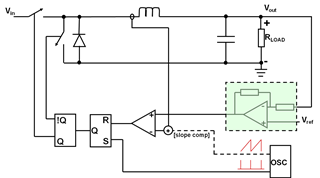
I have some questions about UCC28610 (Frequency and Peak Current Modulated), I am trying to use a QR flyback IC, and I read the TI's document "Exposing the Inner Behavior of a
Quasi-Resonant Flyback Converter" and I have some questions would like to ask you guys. please see my below questions, thanks.

1.) After reading this document, I am still confused about "Frequency Modulated, Constant Current"  or "Frequency and Peak Current Modulated"? Could you please provide an example to me?

From my understanding, we have different input voltage, so the peak current will be different, IC will detect my peak current and modify the switching frequency to implement the QR mode. if yes, why we don't just modify the switching, why we need to also do the peak current modulate?

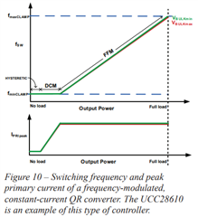
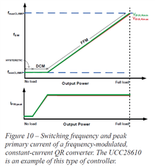
2.) What does this mean "As the output load decreases, the peak current decreases. This makes it very difficult to calculate the switching frequency and peak current at any specific operating point" Could you please provide an example to me?

3. in the FFM, why does the peak current need to help constantly?

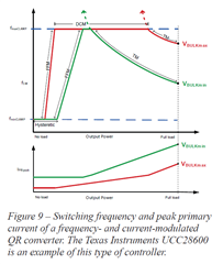
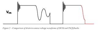
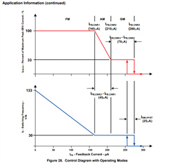
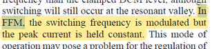
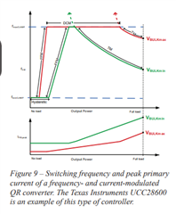
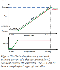
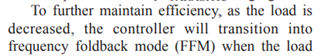
4. I don't understand Figure 10 why FFM is between the mid load and high load, as my understanding, FFM is for light load use to improve the light load efficiency. compare with Figure 9, this is more reasonable to me, and why Figure 10 doesn't have TM mode? Figure 10 can't achieve the QR? because, from figure 2, only TM mode can have lower Vds.

5. In what situation I will need to use "Frequency Modulated, Constant Current" IC or "Frequency and Peak Current Modulated" IC?

Sorry for asking too many questions, but I need to understand them before I use them, hope TI's members could give me some suggestions, thanks.

  • Hello,

    1.

    The UCC289610 only operates at near QR at minimum input voltage maximum duty cycle.  Other wise it is an FM AM modulated DCM controlled flyback.  As the load decreases or the line increases the frequency and peak current will be modulated to control the duty cycle.  This will have waveforms similar to figure 2 that you presented.

    If you want a true flyback controller.  The UCC28600 or LM5023 would be better suited for this application.

    2.  The UCC28610 is a constant on time controller.  At maximum load it will control to a peak current and based on V = L*di/ton and will increase the off time to reduce the duty cycle toff.  The converter does valley swithch.

    When the frequency reaches  30 kHz as the load decreases.  The controller will then reduce the peak current to control the duty cycle.  This is shown in figure 28 above.

    3. The UCC28610 uses valley switching it monitors the aux winding and will detect when the output diode's current reaches 0 and will add delay to before turning of the FET.  This is what is known as valley switching.  Depending on the duty cycle required the device will valley skip with longer dead times looking for when the aux winding crosses 0 V.  Once again the controller will add a delay to valley switch when the FET is turned on.

     4. Where did you get figure 10?  It does not match the UCC28610 data sheet?


    5. Constant current/constant voltage mode flyback controllers such as the UCC28610 are used in battery charging applications.  The output voltage needs constant current to charge a battery from 20% of the regulated output voltage to 100% of the regulated output voltage.

    6. The benefit of using FM/AM modulation over QR is when the load decreases the frequency and peak current decreases to control duty cycle.  This will reduce switching losses from 25 to 100% load improving system efficiency in these power ranges.

    7.  If you want to design a DCM flyback with valley switching, I would recommend that you use the newer UCC28701 and the UCC28711 over the UCC28610 devices. 

    Regards,

  • Hi Mike,

    Thanks for your explanation, but I prefer to know about TI's document "Exposing the Inner Behavior of a Quasi-Resonant Flyback Converter" first?

    is it ok to ask document in here? because I prefer to know the principle and choose the component.

    https://www.ti.com/seclit/ml/slup302/slup302.pdf

    Could you please help to answer questions based on this document? 

    1. What is the difference between "Frequency Modulated, Constant Current"  and  "Frequency and Peak Current Modulated"?

    "Frequency and Peak Current Modulated" : I don't very understand why we need to modulate the Frequency and Peak Current at the same time?

    2. in the "Frequency and Peak Current Modulated" which mention about
    "As the output load decreases, the peak current decreases. This makes it very difficult to calculate the switching frequency and peak current at any specific operating point " on Page 8. why it is difficult to calculate the switching frequency?


    3. I don't understand Figure 10 why FFM is between the mid load and high load, as my understanding, FFM is for light load use to improve the light load efficiency. compare with Figure 9, this is more reasonable to me, and why Figure 10 doesn't have TM mode? Figure 10 can't achieve the QR? because, from figure 2, only TM mode can have lower Vds. on page 8 and page 10.

    4. Why in FFM mode, the current need to be constant? on page 9

    Jack

  • Hello,

    Please see my comments bellow.

    https://www.ti.com/seclit/ml/slup302/slup302.pdf

    Could you please help to answer questions based on this document? 

    >Figure 7 in the paper shows a DCM flyback waveform.  According to this paper this is a QR DCM flyback.  

    >Figure 8 in the paper shows true QR operation.

    >Figure 9 shows how the switching frequency of UCC28600 QR controller behaves. This is not the DCM flyback converter.

    The paper describes the UCC28610 as a QR DCM flyback converter and follows figure 10.

    1. What is the difference between "Frequency Modulated, Constant Current"  and  "Frequency and Peak Current Modulated"?

    > The UC28610 uses frequency modulation (FM) and peak current mode (AM) modulations to achieve a constant current output. 

    >The UCC28610 and UCC28600 both use peak current mode control which will modulate the frequency to control duty cycle.

    >So there is no difference to compare here.


    "Frequency and Peak Current Modulated" : I don't very understand why we need to modulate the Frequency and Peak Current at the same time?

    >The UCC28610 uses peak current (AM) and frequency modulation (FM) to control duty cycle.

    >The UCC28610 does not modulate peak current and frequency at the same time.  Please refer to figure 10.

    >The UCC28600's peak current will vary with load and intern will vary the frequency to control the duty cycle. (Figure 9).  This will occur at the same time and is how the system works to control duty cycle.

    2. in the "Frequency and Peak Current Modulated" which mention about
    "As the output load decreases, the peak current decreases. This makes it very difficult to calculate the switching frequency and peak current at any specific operating point " on Page 8. why it is difficult to calculate the switching frequency?

    > These converter's base switching frequency on primary magnetizing, inductance, load current, efficiency.

    > You should be able to calculate the switching frequency (fsw) at any given time with the following equation with either the UCC28600 or UCC28610.

    Eff = Efficiency, Ipk = primary peak current and Lpm is the transfer primary peak current.  You will need to refer to figure 10 of the UCC28610 when using the UCC28610 to figure out what the peak current should be.  You will need figure 9 for the UCC28600 to figure out what the peak current is.

    Pout

    3. I don't understand Figure 10 why FFM is between the mid load and high load, as my understanding, FFM is for light load use to improve the light load efficiency. compare with Figure 9, this is more reasonable to me, and why Figure 10 doesn't have TM mode? Figure 10 can't achieve the QR? because, from figure 2, only TM mode can have lower Vds. on page 8 and page 10

    >In this paper you attached figure 10 shows the DCM flyback will be a maximum frequency at maximum load.

    >When operating in  FM the peak current will always be the same value at a given input voltage.  As the load decreases the frequency will decrease to maintain the duty cycle and load current.

    Iout = Ipk*(Ns/Np)*ton*fsw

    >When the converter is operating in the AM range it will decrease the peak current at a given input to control the duty cycle.  In this AM range the frequency is fixed.  Please refer to figure 10. 

    4. Why in FFM mode, the current need to be constant? on page 9

    >This is true and this is constant on time control.

    Regards,

  • Hi Mike,

    Thanks for your comment, after I read it. I am still confused about some things.

    Please see my comments below, thanks.

    https://www.ti.com/seclit/ml/slup302/slup302.pdf

    Could you please help to answer questions based on this document? 

    >Figure 7 in the paper shows a DCM flyback waveform.  According to this paper this is a QR DCM flyback.  

    [Jack] : A little confused about the definition, DCM, TM, and FFM all of three are could do the QR operation? if Yes, how to distinguish it?

    >Figure 8 in the paper shows true QR operation.

    >Figure 9 shows how the switching frequency of UCC28600 QR controller behaves. This is not the DCM flyback converter.

    [Jack] : How do I know this is not the DCM flyback converter, according to Figure 9, there is three modes in this figure, TM, DCM, and FFM.

    The paper describes the UCC28610 as a QR DCM flyback converter and follows figure 10.

    [Jack] : On page 9, as the load is decreased, the controller will transition in to FFM mode. why in fiugre 10, the FFM mode will show up in the mid load to full load?

    1. What is the difference between "Frequency Modulated, Constant Current"  and  "Frequency and Peak Current Modulated"?

    > The UC28610 uses frequency modulation (FM) and peak current mode (AM) modulations to achieve a constant current output. 

    [Jack] :

    is Peak Current Modulated equal to Peak Current control mode (AM)?

    Do you mean the peak current mode control like below?


    Because UC28610 is using peak current mode control, so the Ipeak is a constant (Please see below equation), inorder to maintain the Ipeak, so we need to modify the switching frequency, Do I understand correctly?

    frequency modulation (FM) means modifying the frequency like above.

    >The UCC28610 and UCC28600 both use peak current mode control which will modulate the frequency to control duty cycle.

    [Jack] : Same question above.

    >So there is no difference to compare here.


    "Frequency and Peak Current Modulated" : I don't very understand why we need to modulate the Frequency and Peak Current at the same time?

    >The UCC28610 uses peak current (AM) and frequency modulation (FM) to control duty cycle.

    [Jack] : Got it.

    >The UCC28610 does not modulate peak current and frequency at the same time.  Please refer to figure 10.

    [Jack] : Got it.

    >The UCC28600's peak current will vary with load and intern will vary the frequency to control the duty cycle. (Figure 9).  This will occur at the same time and is how the system works to control duty cycle.

    [Jack] : If UCC28600 doesn't use peak current control, how does this IC maintain the output voltage? Do you have any easy block diagram about this control? like the below figure.

    2. in the "Frequency and Peak Current Modulated" which mention about
    "As the output load decreases, the peak current decreases. This makes it very difficult to calculate the switching frequency and peak current at any specific operating point " on Page 8. why it is difficult to calculate the switching frequency?

    > These converter's base switching frequency on primary magnetizing, inductance, load current, efficiency.

    > You should be able to calculate the switching frequency (fsw) at any given time with the following equation with either the UCC28600 or UCC28610.

    Eff = Efficiency, Ipk = primary peak current and Lpm is the transfer primary peak current.  You will need to refer to figure 10 of the UCC28610 when using the UCC28610 to figure out what the peak current should be.  You will need figure 9 for the UCC28600 to figure out what the peak current is.

    [Jack] : UCC28610 is peak current mode control, so I can know the Ipeak value and then I can know the switching frequency, do I understand correctly?

    UCC28600 is not a peak current mode control, so I can't know the Ipeak value at any time, so it is difficult to calculate the switching frequency, do I understand correctly?

    3. I don't understand Figure 10 why FFM is between the mid load and high load, as my understanding, FFM is for light load use to improve the light load efficiency. compare with Figure 9, this is more reasonable to me, and why Figure 10 doesn't have TM mode? Figure 10 can't achieve the QR? because, from figure 2, only TM mode can have lower Vds. on page 8 and page 10

    >In this paper you attached figure 10 shows the DCM flyback will be a maximum frequency at maximum load.

    [Jack] : UCC28610 is peak current mode control, why in DCM mode, the input current is not a constant value?


    >When operating in  FM the peak current will always be the same value at a given input voltage.  As the load decreases the frequency will decrease to maintain the duty cycle and load current.

    Iout = Ipk*(Ns/Np)*ton*fsw


    [Jack] : Do you mean in FFM mode the controller is peak current mode control, but in DCM mode the controller is not a peak current control mode?

    >When the converter is operating in the AM range it will decrease the peak current at a given input to control the duty cycle.  In this AM range the frequency is fixed.  Please refer to figure 10. 

    [Jack] : Same question above.

    4. Why in FFM mode, the current need to be constant? on page 9

    >This is true and this is constant on time control.

    [Jack] : Got it.

    Jack

  • Hello Jack,

    Please note that I did not author this paper and don't believe figure 10 is correct.  The UCC28610 will operate near critical conduction/QR max load minimum line and will be operating at maximum frequency.  Every where else the UCC28610 operates will be deep into DCM. 

    Please seem my comments below.

    https://www.ti.com/seclit/ml/slup302/slup302.pdf

    Could you please help to answer questions based on this document? 

    >Figure 7 in the paper shows a DCM flyback waveform.  According to this paper this is a QR DCM flyback.  

    [Jack] : A little confused about the definition, DCM, TM, and FFM all of three are could do the QR operation? if Yes, how to distinguish it?

    >DCM stands for discontinues conduction current mode

    >TM stands for transition mode 

    >FFM is frequency modulation

    >According to the author they are all QR.

    >Figure 8 in the paper shows true QR operation.

    >Figure 9 shows how the switching frequency of UCC28600 QR controller behaves. This is not the DCM flyback converter.

    [Jack] : How do I know this is not the DCM flyback converter, according to Figure 9, there is three modes in this figure, TM, DCM, and FFM.

    >QR converter due run in transition mode

    >This QR controller does not use frequency modulation per the QR data sheet.

    >You need to check the QR or QR DCM flyback controller data sheet to see which control scheme it uses, TM, DCM, FFM etc...

    The paper describes the UCC28610 as a QR DCM flyback converter and follows figure 10.

    [Jack] : On page 9, as the load is decreased, the controller will transition in to FFM mode. why in fiugre 10, the FFM mode will show up in the mid load to full load?

    >Full Load, max duty cycle, frequency is  fmax on the graph to the right.

    >No Load is minimum frequency, duty cycle on the left of the graph.

    >Please note the graph is in error.  This converter is always operating in DCM.

    1. What is the difference between "Frequency Modulated, Constant Current"  and  "Frequency and Peak Current Modulated"?

    > The UC28610 uses frequency modulation (FM) and peak current mode (AM) modulations to achieve a constant current output. 

    [Jack] :

    is Peak Current Modulated equal to Peak Current control mode (AM)?

    >Peak current mode control is a when the peak current is used instead of PWM ramp to control the duty cycle.

    >These devices do use peak current mode control.

    >How they control the peak current is described in the paper.

    Do you mean the peak current mode control like below?

    >I am not sure where you got the below plot but it does not look correct for a peak current mode control buck converter.

    >The CS signal looks like a PWM ram and not the CS signal of a buck converter.


    Because UC28610 is using peak current mode control, so the Ipeak is a constant (Please see below equation), inorder to maintain the Ipeak, so we need to modify the switching frequency, Do I understand correctly?

    frequency modulation (FM) means modifying the frequency like above.

    > I don't think this equaitohn is correct.  Please refer to the UCC28610 data sheet for the correct one.

    >The UCC28610 and UCC28600 both use peak current mode control which will modulate the frequency to control duty cycle.

    [Jack] : Same question above.

    >The UCC28600 Lm does set the frequency but is true QR control.  It turns of the FET when the current reach's zero when the transformer is deenergized.  And turns the FET on when a peak current is reached.  The paper you are refereeing to describes this in more detail. 

    >So there is no difference to compare here.


    "Frequency and Peak Current Modulated" : I don't very understand why we need to modulate the Frequency and Peak Current at the same time?

    >The UCC28610 uses peak current (AM) and frequency modulation (FM) to control duty cycle.

    [Jack] : Got it.

    >The UCC28610 does not modulate peak current and frequency at the same time.  Please refer to figure 10.

    [Jack] : Got it.

    >The UCC28600's peak current will vary with load and intern will vary the frequency to control the duty cycle. (Figure 9).  This will occur at the same time and is how the system works to control duty cycle.

    [Jack] : If UCC28600 doesn't use peak current control, how does this IC maintain the output voltage? Do you have any easy block diagram about this control? like the below figure.

    2. in the "Frequency and Peak Current Modulated" which mention about
    "As the output load decreases, the peak current decreases. This makes it very difficult to calculate the switching frequency and peak current at any specific operating point " on Page 8. why it is difficult to calculate the switching frequency?

    > These converter's base switching frequency on primary magnetizing, inductance, load current, efficiency.

    > You should be able to calculate the switching frequency (fsw) at any given time with the following equation with either the UCC28600 or UCC28610.

    Eff = Efficiency, Ipk = primary peak current and Lpm is the transfer primary peak current.  You will need to refer to figure 10 of the UCC28610 when using the UCC28610 to figure out what the peak current should be.  You will need figure 9 for the UCC28600 to figure out what the peak current is.

    [Jack] : UCC28610 is peak current mode control, so I can know the Ipeak value and then I can know the switching frequency, do I understand correctly?

    UCC28600 is not a peak current mode control, so I can't know the Ipeak value at any time, so it is difficult to calculate the switching frequency, do I understand correctly?

    3. I don't understand Figure 10 why FFM is between the mid load and high load, as my understanding, FFM is for light load use to improve the light load efficiency. compare with Figure 9, this is more reasonable to me, and why Figure 10 doesn't have TM mode? Figure 10 can't achieve the QR? because, from figure 2, only TM mode can have lower Vds. on page 8 and page 10

    >In this paper you attached figure 10 shows the DCM flyback will be a maximum frequency at maximum load.

    [Jack] : UCC28610 is peak current mode control, why in DCM mode, the input current is not a constant value?


    >When operating in  FM the peak current will always be the same value at a given input voltage.  As the load decreases the frequency will decrease to maintain the duty cycle and load current.

    Iout = Ipk*(Ns/Np)*ton*fsw


    [Jack] : Do you mean in FFM mode the controller is peak current mode control, but in DCM mode the controller is not a peak current control mode?

    >When the converter is operating in the AM range it will decrease the peak current at a given input to control the duty cycle.  In this AM range the frequency is fixed.  Please refer to figure 10. 

    [Jack] : Same question above.

    4. Why in FFM mode, the current need to be constant? on page 9

    >This is true and this is constant on time control.

    [Jack] : Got it.

  • Hi Mike,

    I will read UCC28610 in more detail, thanks.

    Jack

  • Hello Jack,

    I was glad that I could help.

    Regards,

    Mike