This thread has been locked.

If you have a related question, please click the "Ask a related question" button in the top right corner. The newly created question will be automatically linked to this question.

UCC28710: Figure 16.

Part Number: UCC28710

Hello,

I would like to calculate some parameters on UCC28710 and must make sure a behavior of frequency at some load conditions.

My question is:

a)In my understanding, the below condition is needed for starting constant-current mode. Is it correct?

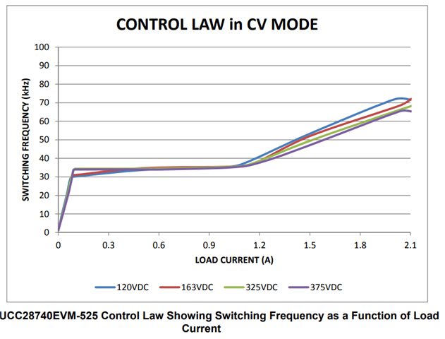
    -Either the Switching frequency must be reached to 100kHz or the Dmag must be reached to duty cycle 0.425.

    -The drain current of primary MOSFET must be reached IPP max.

b)If it is correct, in the case of 66kHz being set to target full-load maximum switching frequency, the constant-current mode of output load becomes set at 150% of nominal. Is it correct? 

c)If it is correct, how is the below tolerance?

    -DMAGCC (0.425 +? -?)

    -The switching frequency on the amplitude modulation mode area (33kHz +? -?)

d)What is the" fMIN" on section 12.1.2.3 of the datasheet? And how do I calculate it? 

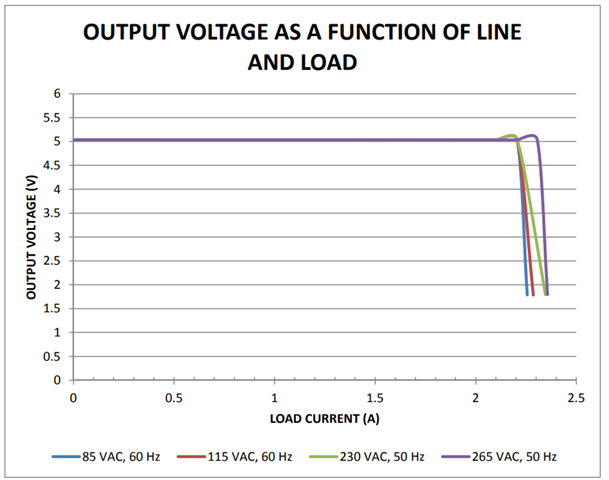
e)What is "VCCR"? Is this minimum of VCST at the constant-current mode? For example, which implies the condition of around 2V on figure 18's lowest point of output voltage.

Best regards,

Shintaro

  • Hi Shintaro-san,

    Thank you for the query.

    a) You are correct that in constant current mode the Dmag must be close to 0.425 and the primary peak current must be close to Ipp(max). The equation for current output is Iout=0.5*Ipp(max)*Nps*(tdemag/tsw). We can roughly substiute for the case shown in excel calculator for the tool where Nps=14.13, Ipp(max)=0.35 and Dmag=0.425 and get close to 1A. The transformer primary inductance and primary peak current chosen sets the maximum operating frequency of the converter as clarified in equation 16 of the datasheet. 

    b) If you have designed you system for max. Fsw of 66Khz, your max. switching frequency will be 66Khz when it jumps into CC mode as per the design calculator by your choice of inductance and Rcs value and not 100Khz. The following shows an evm designed for 71Khz and shows the profile and the current is maintained constant (as per the equation discussed in point a where duty will be fixed at 0.425) and voltage is reduced and it will not increase to 150% of nominal

    c) I am not sure on the tolerance and it is not described in the datasheet

    d) Fmin is calculated based on preload resistor and rough estimate of efficiency for stanby power case. If you check the datasheet, equation -7 we can get fmin. Pstanby can be roughly estimated as the product of Vocv and Istandby (target value). Substituting this reduces the above equation to Fmin = efficiency*(Kam)^2*Fmax*Istandby/Iocc

    e) Vccr is the constant current regulating level (around 330mV) specified in the datasheet and is used for calculating the Rcs value. Vcst (min) is the minimum current pulse amplitude applied at AM region at light load.

    Please let me know if you have any clarifications.

    Regards,

    Harish

  • Hi Harish,

    Thank you for your reply. it helps me to understand. I have more questions.

    a) If it is correct, the value of constant-current or the fmax must be dependent on the input voltage. Because the fsw can be calculated with Rcs, Vcst=0.78V, and Lp under DCM conditions. However, your first picture mentions that the fsw is constant between max and minimum input voltage despite Ipp and Dmag not being changed. How do you manage the fsw with changed input voltage?

    b) It is related to a).

    c) Thank you.

    d) Thank you.

    e) My question is:

    Is the value of Vccr constantly under the constant-current mode operation? Or is it in proportion with something?  Could you please describe how you control constant-current?

    Best regards,

    Shintaro

  • Hi Shintaro-San,

    Thank you for the reply.

    For the first part of the question, the UCC28710 can maintain tight constant-current regulation over input line voltage by utilizing the line compensation feature where line compensation resistor Rlc is calculated as per equation 27 of the datasheet. The first picture mentions the operation in CV mode and shows the variation of switching frequency as per control law. Current modulation is not shown. As you increase the load and you are in FM and there is variation in Fsw over line for load over 1.1A as seen in figure.

    Yes the Vccr is close to 330mv (with 5% variation) in constant curent mode operation. In the constant current mode the primary current will be corresponding to Ippmax, turns rartio will be fixed and our only parameters to control current are secondary demag time and Fsw as per equation 6 of the datasheet. When the average output current reaches the regulation reference in the current control block, the controller operates in frequency modulation mode to control the output current at any output voltage at or below the voltage regulation target. So effectively demagnetising time will be a proportion of Fsw (which was 0.425 in my previous example) and will maintain the output current as load is increased.

    Thank you

    Regards,

    Harish

  • Hi Harish-san

    Thank you for your explanation. Let me confirm whether my understanding is correct or not. 

    -The Ipp should be a constant value between low and high input voltage range to keep the same condition of magnetizing the transformer if the load condition is not changed.
    And that has been achieved with compensating function and delay time even though it exceeds the Vcst(max).

    -In constant current mode, Vccr is controlled by law block to be 330mV with tsw and tdm(Might be output voltage).

    And let me ask a question more. Equation 14 comes from 6 with exchange from IPP to Vccr and Rcs.
    But why is ηXFMR square rooted? And why are tdm and tsw disappearing? Please explain that.

    Best regards,
    Shintaro

  • Hi Shintaro-San,

    Thank you for the query. 

    Yes, you are correct with your thoughts and explanation.

    tdm is a fraction of the switching period tsw and this fracton will be controlled to a value of 0.425 and hence it disappears.

    Regarding the sqrt in the transformer efficiency, I will have to check and will let you know if have an answer to this in the next couple of days.

    Regards,

    Harish 

  • Hi Shintaro-San,

    I am not sure on the derivation of square root of efficiency term which we see in the Rcs equation, but rearranging terms shows that Vcst(max)*(tmag/tsw) = Vccr*sqrt(eficiency)

    When Vcst(max) is 780mv and tmag/tsw ratio is 0.425, the product of these terms is close to 331mv which is equal to the value of Vccr. The efficiency term should not adversely affect the choice of sense resistor. 

    Thank you

    Regards,

    Harish

  • Thank you! It is valuable!

  • Hi Shintaro-San,

    Thank you for the valuable feedback. 

    Regards,

    Harish