This thread has been locked.

If you have a related question, please click the "Ask a related question" button in the top right corner. The newly created question will be automatically linked to this question.

UCC28070A: VRMS setup

Part Number: UCC28070A
Other Parts Discussed in Thread: UCC28070

Hi Team,

Our customer has a question regarding the UCC28070A, which is how can we use this IC to set at a particular Vrms when you can achieve max power or only half of the max power? Does it seem like it's done with the multiplier IMO current setting? is this right?

For instance, when you are above 200Vrms the user can supply max power, and below 200Vrms only half of the max power, or is that not a feature this IC supports?

Thank you in advance. 

Best regards,

Jonathan

  • Hi Jonathan,

    Thank you for the query. I am currently working on this and I had run into MATHCAD licensing issues. I will come back to you by tomorrow.

    Regards,

    Harish

  • Hi Jonathan,

    Yes you are correct that it has to be done with respect to the IMO multiplier setting. The RIMO resistor has to be varied depending on the line condition below which you will want to reduce the power by half.

    Let me explain with a simple example. Imagine that you have designed your system as per the excel calculator and have the following values for Pout = 1320W, Rs=23.7ohms, Rimo=24.3k,  Nct =100, efficiency=0.95 and Vvao (max)=5V - which is the parameter controlling the power output.

    The variation of Vvao based on output power and input voltage quantization bin levels is given by the following formula:

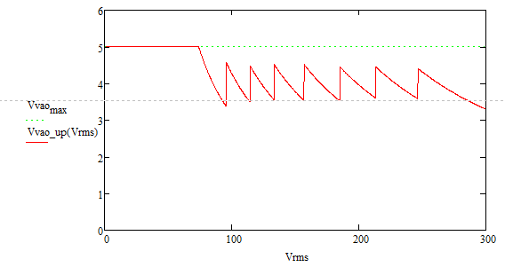
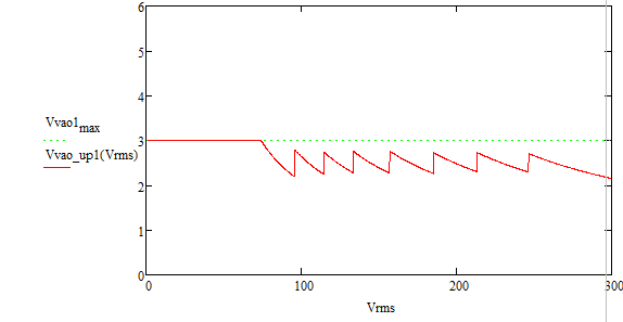
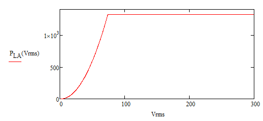
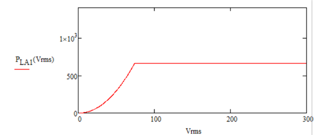
    The following figures show the graphical variation when Pout is at full load and then reduced to half it rated value. We can see Vvao reduces nearly by factor.

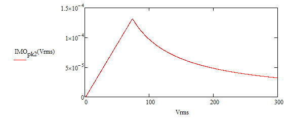
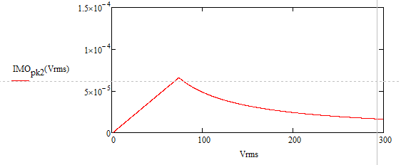
    Now if we calculate Imo current for the two cases using the following equation,

    The power delivered is varies as Imo current and can be seen below: 

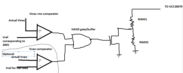
    What you will need to do is combine both these cases using comparators and logic externally to change Rimo to control output power depending on input voltage. One possible implementation 

    Hope this helps .

    Thank you

    Regards,

    Harish

  • Hi Harish, I can't thank you enough for the time you spent and how thoroughly you answered the question.

    Just as an FYI, this is my first universal PFC design.

    I do have some questions still remaining though:

    1) Would you be able to give your function definitions of Vvinac_pk(Vrms) & Kvff_up((Vrms)?

    2) I've read over the Quantization Voltage Feed Forward section of the UCC28070A a few times now, and I'm having troubles with understanding something you've touched upon here. I've highlighted the paragraphs that I'm getting confused by, but more specifically what do these statements mean when they say lowest and highest maximum power levels per Qvff. I think the first two data sets you plotted are highlighting these comments. 

    My understanding of Qvff and why it is needed and how to use is it quite limited. I see the equations but I don't have an intuitive understanding.


  • Hi William,

    Thanks for the kind words. 

    1. Sure we can definitely share the function definitions but these are obtained by rearranging terms 13, 14 and 18 in datasheet. I will do it in a day or two because of a mathcad issue.

    2. Within a particular bin, let's say we take bin 2 where Vinac(pk) is between 1 & 1.2V. Now the Kvff is a constant which represents a scaled value of square of input voltage at the center of bin. So it will be ((1+1.2)/2)^2/1.414 = 0.6. The value 1.414 is to convert peak to rms value. Now within a particular bin this value will be constant, now if your input voltage fall either side of this center value Vvao is adjusted either upwards or downwards to compensate. That is why you see the triangluar shape of Vvao as in the first graph which I attached.

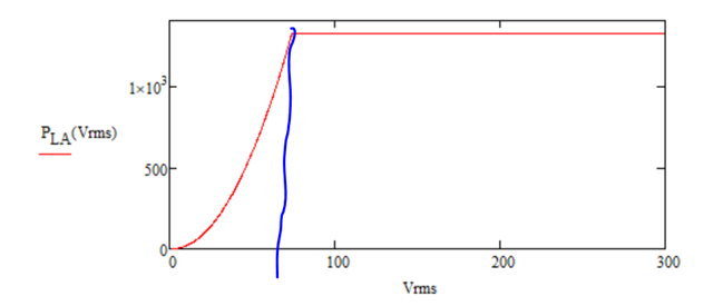
    The blue line below corresponds to Vinac of around 0.76 below which we see the power linearly falling to zero as input voltage is decreased. The variation of IMO is between 130uA and 171uA shown in the datasheet, Vvao adjusts as shown in the previous figure by increasing and decreasing to maintain the power level. If Vvao was set to its max. value of 5V, then lower power will correspond to the lower limit of the bin and higher power will be other extreme within the bin.

    Please let us know if you have questions.

    Thank you

    Regards,

    Harish

  • Hi Harish,

    Any update on those functions?

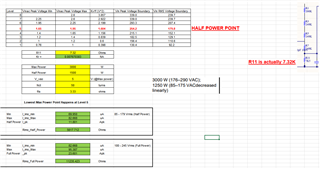
    I've attached a spreadsheet showing my first stab at calculating an RIMO resistor value that would ensure the PFC stage only output 1500W up to 179Vrms.

    Let me explain what I did and see if you think it makes sense or not.

    I first revised the Vin peak voltage boundary since my output is 390, with a Kr of 0.00767. Converted that to RMS (far right column) and found which level I want to make my Half power to full power limit. I chose level 5 which is highlighted in red.

    Then, I calculated I_imo by (17*E-6 * 1.65 * (5-1))/(1.604) = 69 uA.

    Then, calculating I_pk at an output power of 1500W, (1500/179)*SQRT(2) = 11.8 Arms.

    Then using Rimo equation, (0.5* 11.8 * 3.33)/(50 * 69E-6) = 5.6k.

    So, my understanding by calculating this Rimo value is that by using 5.6k, this will only allow 1500W up to around 179Vrms. ("Rimo_Half_Power").

    I then redo that procedure, but, now use level 6 Vinac values (1.95 & 2.25) to calculate I_imo, then calculate I_pk, and lastly "Rimo_Full_Power".

    So, looking at your Diagram, I would then make Rimo1 = 5.6k, and Rimo2 = 5.6k.

    Let me know if my calculations or understanding is wrong or right, thanks Harish!

  • Hi William,

    Sorry for my late reply. Your concept to vary RIMO based on the target power level is fine. I think the levels chosen is also ok. So based on this UCC28070 will power limit from level1-level5 based on 1250W corresponding to Rimo1 and then for next higher power of 3000W will be based on Rimo1 and Rimo2.  Please find my attached pdf version of mathcad file. It can be unorganized as I just print out MATHCAD to pdf format.

     mathcad.pdf

    Please let me know if you have any further questions.

    Regards,

    Harish