This thread has been locked.

If you have a related question, please click the "Ask a related question" button in the top right corner. The newly created question will be automatically linked to this question.

BQ25100: BQ25100 Oscillations at Startup

Part Number: BQ25100

Hi,

We have a design incorporating the BQ25100 to charge a small, 35mAh battery.

We have made about 80 units so far, with another 100 in progress. We are planning a small production run later this year of 5,000 units.

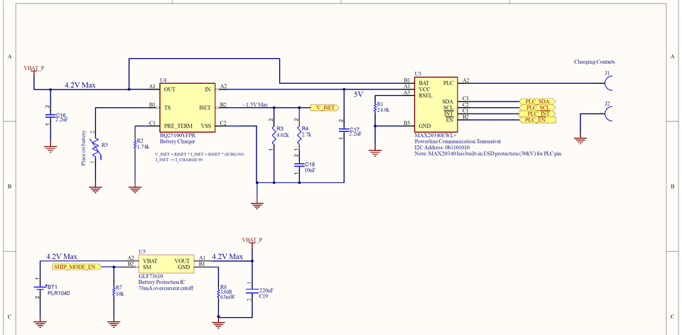
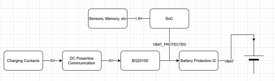
Our battery charging path is shown in the simplified block diagram below:

A few notes about the design:

  • The battery is a 35mAh rechargeable LiPo battery
  • The battery is non-removable
  • We have placed a compatible 10k NTC thermistor on the area where the battery gets soldered to the board

When the battery is soldered on, the battery protection IC keeps the VBAT and VBAT_PROTECTED nets cut off from each other. This is also the case if the battery is depleted to less then 2.8V (undervoltage protection), short-circuited, or if "ship mode" is entered.

To wake the protection IC from this cutoff state, a charge voltage of at least 3.6V must be applied to VBAT_PROTECTED. The protection IC will then latch on and connect VBAT to VBAT_PROTECTED.

Our system also incorporates an SoC that has internal regulators set to 1.8V, which powers various other sensors and devices (all come up in low power states so they do not draw much current). The SoC is permanently connected to VBAT_PROTECTED and so it powers on immediately when the BQ25100 begins to output a voltage.

The issue we are seeing:

In some devices, some of the time, the VBAT_PROTECTED net oscillates when 5V is applied to the input of the BQ25100. This prevents VBAT_PROTECTED from developing the necessary 3.6V to latch on the protection IC, and the device never fully powers up.

We have tried a number of things, including disconnecting the SoC, keeping the SoC in reset, increasing the charge current to 80mA from 35mA, removing the NTC to put the BQ25100 in TTDM mode, all to no avail.

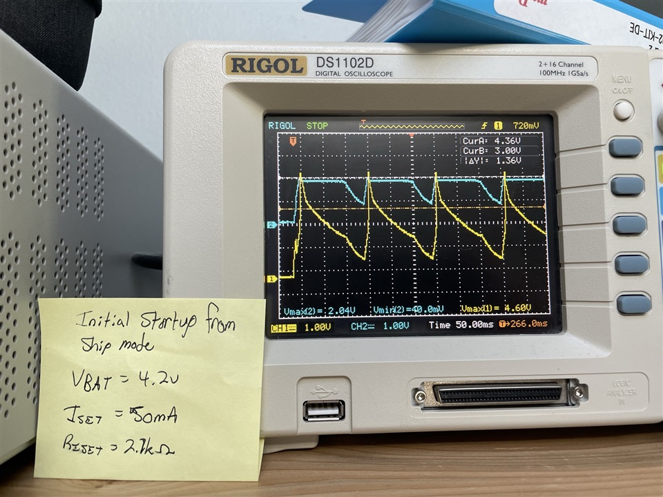
An example of the oscillation we are seeing is below. The yellow trace is the VBAT_PROTECTED voltage, and the blue trace is our 1.8V system voltage.

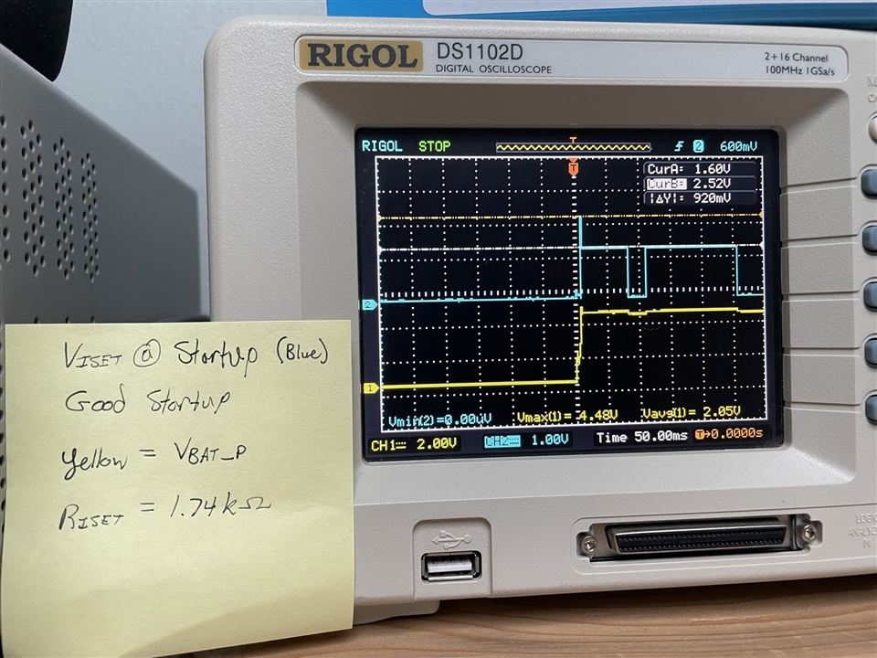
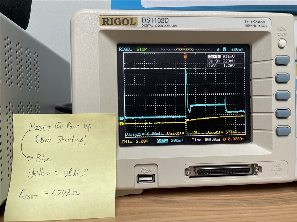
We probed VISET on two units, one exhibiting startup issues and one that starts up fine. The blue trace is VISET, the yellow trace is VBAT_PROTECTED. The left image shows a good startup, the right image shows a bad startup.

A peculiar behavior is that when we heat up the boards (ie: reflow the BQ25100) the device will sometimes startup properly for a while, up to an hour, but then revert to this state.

I can share more specific details and schematics, but I would like to do so via email and get a proper NDA in place.

  • Hi George,

    The first thing come to my mind is the device has a battery detection routine if battery is not presented. In your block diagram, the battery protection IC disconnects OUT pin on the BQ25100 and the battery. When in put plugged in, the IC will perform battery protection which OUT pin will be a square waveform. This might cause some issue on closing the FET in the protect IC.

    Would you please also share the scope capture on the OUT pin? One thing to try is to connect the battery at the OUT pin directly to see if the issue still occurs. 

    Also what is the voltage on TS pin? 

    Can you share the charger portion of the schematic?

  • Hi Jing Zou,

    Please see an excerpt of the charging path for our device:

    The actual part number for U5 is GLF73915-AD12C. NOTE: The schematic mentions a 76mA overcurrent cutoff, this is not the case with the GLF73915. Ignore that statement.

    We have routed V_ISET to an ADC input on our microcontroller.

    The MAX20340 is a DC powerline communication transceiver. Essentially, it outputs 5V onto the VCC pin when 5V is applied to the PLC pin. This issue occurs even when we do not use the PLC features of the chip.

    Following that is the BQ25100, which is essentially the reference schematic verbatim. We have the suggested RC network on the ISET pin because our charge current setting is below 50mA (set to 35mA).

    The NTC part number is Panasonic ERT-J0EG103FA, which I selected to conform to what the BQ25100 expects.

    The protection IC integrates the FETs required for battery isolation. It is supposed to turn on when the VBAT_P net (on its VOUT pin) reaches 3.6V or higher, so the battery detect routine of the BQ25100 should trigger this.

    I can capture more oscilloscope traces and current draw traces if you need more info.

    I see a similar issue in the forums: https://e2e.ti.com/support/power-management-group/power-management/f/power-management-forum/912335/bq25100-will-not-charge-or-stops-charging-unexpectedly?tisearch=e2e-sitesearch&keymatch=BQ25100#

    I am not sure what the solution was for that user.

    I look forward to hearing back.

  • Hi George,

    Thank you for the provided information. The schematic outside of the DC Powerline Communication Transceiver is good. It may be best to move this conversation over to Email in order to continue debugging. I have sent you a friend request including my email.

    Best Regards,

    Juan Ospina