This thread has been locked.

If you have a related question, please click the "Ask a related question" button in the top right corner. The newly created question will be automatically linked to this question.

LM5156H: Webench and Pspice simulation - LM5156HPWPR

Part Number: LM5156H
Other Parts Discussed in Thread: LM5155

Hi Ti Team,

1134.WBDesign34.pdf

Through aid of Ti Webench I could design Boost Converter for below specifications

Input Voltage: 10V to max 17V 

Output Voltage: 24V, 3A 

Switching frequency - 460KHz  

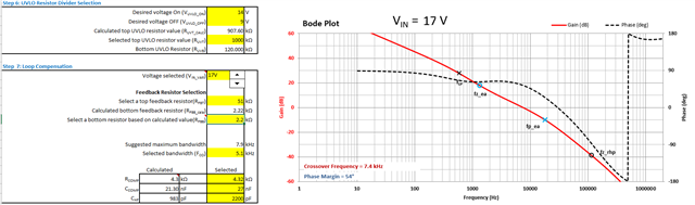
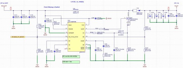
With Resistor divider circuit at FB pin 51k and 2.2k and board works fine (Pls refer report attached and sch image) 

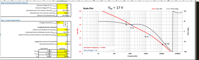
Now I would be like to change it to 510k and 22k respectively to reduce current consumption.


As there is no option to simulation and verify webench could you help on this regard ? 

Will it be any concern if change of resistor ?

  • Hello Hemalatha,

    Thanks for reaching out to us via e2e.

    When you change the upper feedback resistor it will have an influence on the compensation.

    Webbench Designer is a good tool to give you an im pression how a design can basically look like.
    Indeed it does not re-calculate the compensation components, even if you introduce custom parts for the feedback divider.

    For a proper calculation of the external components, please use the LM5155/56 Boost Controller Quick Start Calculator (Rev. B),
    which you can find on our website.

    Best regards,
    Harry

  • Hi Harry,

    Thanks for your response

    With existing part

    With change of resistors

    Could you please explain about maximum bandwidth and FCO 

    should it be more than recommended ? how would it affect on operation 

    Thanks in advance

  • Hello Hemalatha,

    I am sorry, I am very busy at the moment. I will have a look at it and come back to you at the beginning of next week.

    In the meantime, can you please do me a favor and provide me with the full set of parameters that you have filled in into the yellow field for both options? 

    Thanks and regards,
    Harry

  • Hello Hemalatha,

    The Quick Start Calculator shows that changing the resistor divider to 510k and 22k does not make much of a dfference (less than I had expected).

    The best crossover frequency should be determined in the lab on a real board.
    Ringing should be reduced but transients should not be over-compensated.

    Here is a document that explains the theory:
    https://www.ti.com/seclit/ml/slup340/slup340.pdf

    This is an extract from that document:
    Although higher crossovers are generally preferable, there are practical limitations.
    The rule of thumb is one-fifth to one-tenth the switching frequency.
    Attenuation at the switching frequency is also important for noise immunity to minimize jitter. 
    The gain should ideally pass through zero with a slope of –20 dB/decade.
    This will maximize gain margin and will also negate the chance of the gain turning positive at a higher frequency where the phase may be going through zero.
    If that happens, you could have an unstable control loop

    Best regards,
    Harry

  • Hello Hemalatha,

    I have not heard from you for a while now, so I assume your problem has been solved and I will close this thread.
    You can re-open it or simply start a new one if this one got locked.

    Best regards,
    Harry