This thread has been locked.

If you have a related question, please click the "Ask a related question" button in the top right corner. The newly created question will be automatically linked to this question.

TPS61178: TPS61178

Part Number: TPS61178
Other Parts Discussed in Thread: TPS61288, LM3488, LM3478, LM3481, LM3481-Q1, LM5176, LM34936, LM34936-Q1, LM5118, LM25118, LM5176-Q1, LM25118-Q1, LM5118-Q1

Hi TI Team,

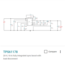
Earlier, We have communicated with TI Team regarding the TPS61178 switcher part and they were given confirmation for TPS61178.

e2e.ti.com/.../4148405

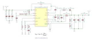
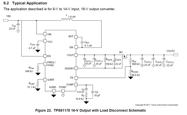
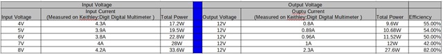
We are giving 3.0V to 4.2V supply to the switcher and we want to generate 12V, 2A from this switcher. I am attaching our circuit diagram for your reference and we have already verified the schematic with TI earlier.

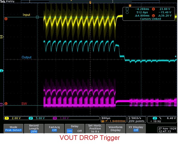
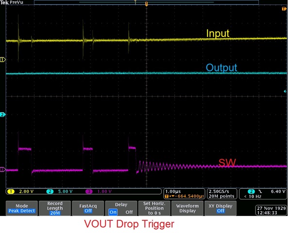
Board is restarted when the current output is >0.5 A.

We have connected resistive load to the switcher output and increased the load slowly and when it is reached at 0.6A, the board is restarted so switcher is giving 12V, 0.6A output only when the input voltage is 3.8V.

So please provide your technical guidance for the same. We want 12V, 1.2A stable output. Board is already designed and our hand.

  • Hi Ritesh,

    Sorry for the wrong link.

    try this Power Designer (ti.com), type the input and output then click UPDATE DESIGNS

    it will show all the reference designs, you can choose converter(integrated switch)  or controller (external switch).

    Click any design to see details.

    Best Regards

    Fergus

    Hello ,

    There are total 16 solutions are coming as per proper input and output selection and i found that TPS61178 is also coming into that solution.

    So, We are little bit confused that how we can evaluate it based on past experience of TPS61178 as we are facing right now. 

    Power Designer (ti.com)

    Would you please help us to evaluate from your end as per input and output requirements for our product which will be really helpful for us to move further with quick way?

    Regards,

    Ritesh Prajapati

  • Hello ,

    We have also checked from TI Power Design link and found following suggested part as per our requirements
    TI Suggested Part for Input 3V to 4.2V and Output 12V 2A
    1. LM3488 : 2.97V to 40V Wide Vin Low-Side N-Channel Controller for Switching Regulators
    2. LM3478 : 2.97-40V Wide Input Range Boost/SEPIC/Flyback DC-DC Controller
    3. LM3481 : 2.97V to 48V High-Efficiency Controller for Boost, SEPIC and Flyback
    4. LM3488-Q1 : 40-V wide VIN low-side N-channel controller for switching regulators with 5-A shutdown current
    5. LM3481-Q1 : 2.97-V to 48-V high-efficiency controller for boost, SEPIC and flyback, AEC-Q100 qualified
    6. TPS61288 : 18V, 15A synch boost converter
    7. TPS611781 : 20-V, 10-A fully integrated sync boost with load disconnect
    8. TPS61178 : 20-V, 10-A fully integrated sync boost with load disconnect
    9. LM5176 : 55V wide VIN synchronous 4-switch buck-boost controller
    10. LM34936 : 30-V Wide VIN Synchronous 4-Switch Buck-Boost Controller
    11. LM34936-Q1 : Automotive, 30-V wide VIN synchronous 4-switch buck-boost controller
    12. LM5118 : 3-75V Wide Vin, Current Mode Non-Synchronous Buck-Boost Controller
    13. LM25118 : 3-42V Wide Vin, Current Mode Non-Synchronous Buck-Boost Controller
    14. LM5176-Q1 : 55-V wide VIN synchronous 4-switch buck-boost controller, AEC-Q100 qualified
    15. LM25118-Q1 : 3-42-V wide VIN, current mode non-synchronous buck-boost controller, AEC-Q100 qualified
    16. LM5118-Q1 : 3-V to 75-V wide VIN, current mode non-synchronous buck-boost controller
    So, We have already validated TPS61178 and not getting actual output while connecting inductive load. 
    Would you please suggest any 2 to 3 parts from above list to go and evaluate as per our requirements which will be really helpful for us?
    Regards,
    Ritesh Prajapati
  • Hi Ritesh,

    The design depends on your demands.

    You can use the filters to screen them。

    For example, I wish to use the footprint minimum, then there are only three solution left.

    if we want to use TPS61178 ,then click the schematic

    you can see all the reference design.

    you can also see the BOM and charts.

    Click Customize design you can see the PCB reference design.

    You can compare this to your current design or to refer to this to make a new design

    You can click other solutions to have a compare.

    Regards

    Fergus

  • Hello ,

    Thanks for details explanation. 

    As you already know our input requirements and output requirements. So, Would you please suggest appropriate at-least 2 to 3 parts from total 16 listed parts?

    So that we can have idea to evaluate it as per your recommended parts. We need that kind of support from your end if you can suggest us.

    Regards,

    Ritesh Prajapati

  • Hi Ritesh,

    It's just like we discussed before.

    Please have a detail waveform with the Vin(PIN 12) ,SW(PIN7),  and VOUT(PIN 8)  in one picture.

    Use the Vout drop to trig the waveform (single mode is recommended) and choose appropriate time axis, sampling point and ACQ to make sure we can see every SW waveform clearly(like the picture I attached before).

    If you are still confused how to capture , please raise your detail questions about the testing.

    Thanks 

    Fergus

    Hi Fergus,

    We have captured the waveform as per your requirement. Let me know if you require any other waveform.

    We have also carried out one more test from our side. We have given the extern supply to the switcher and noted down the result.

    We have taken 9.2 Typical Application reference design from the datasheet and changed all the components as per the reference design.

    We have started to provide from 4V input voltage and increase the voltage by 1V. We have got the 12,2A output once the input voltage reaches 8V. Please find the attached test result image.

    As per the test result, we can identify that switcher is giving around 50% efficiency only, and when the input supply reaches 8V than switcher is giving around 80% efficiency. so our question is why is the switcher not giving 80% efficiency <7 V input voltage? It is due to switcher limitation or is there any role of layout design?

    Thanks,

    Ritesh

  • Hi Ritesh,

    For my side, it is recommended you use the three solution:

    1. TPS61288 : 18V, 15A synch boost converter
    2. TPS611781 : 20-V, 10-A fully integrated sync boost with load disconnect
    3. TPS61178 : 20-V, 10-A fully integrated sync boost with load disconnect

    The three do not need external switches and will cost less.

    Regards

    Fergus

  • Hi Ritesh,

    Thank you a lot for the waveforms.

    One questions: if the waveforms are tested in extern supply and EVM board?

    One certain existed problem. in 1st picture ,we can see the output drops when the input drops, because the low input voltage reach the UVP and cause the chip to stop output.

    It is possible that the input resistor is too large. Please have a check why the input voltage is not stable.

    You can use short and thick wires connecting directly from power supply to input , that will help much.

    As for the efficiency, the chip working in the ON/OFF alternate situation will definitely lower the efficiency.

    It is recommended you solve the shut down issue first. Once the problem is solved, the efficiency will be normal.

    Best Regards

    Fergus

  • Hi Ritesh,

    For my side, it is recommended you use the three solution:

    1. TPS61288 : 18V, 15A synch boost converter
    2. TPS611781 : 20-V, 10-A fully integrated sync boost with load disconnect
    3. TPS61178 : 20-V, 10-A fully integrated sync boost with load disconnect

    The three do not need external switches and will cost less.

    Regards

    Fergus

    Hello, 

    Thanks for providing suggestions. 

    We have checked stock for TPS61288 but not able to get from anyone. 

    Also we ar right now facing issues into TPS61178 so we are not comfortable to order it again. 

    Do you have any other suggestions apart from above which can fulfil our requirements? 

    Regards, 

    Ritesh Prajapati

  • Hi Ritesh,

    Thank you a lot for the waveforms.

    One questions: if the waveforms are tested in extern supply and EVM board?

    One certain existed problem. in 1st picture ,we can see the output drops when the input drops, because the low input voltage reach the UVP and cause the chip to stop output.

    It is possible that the input resistor is too large. Please have a check why the input voltage is not stable.

    You can use short and thick wires connecting directly from power supply to input , that will help much.

    As for the efficiency, the chip working in the ON/OFF alternate situation will definitely lower the efficiency.

    It is recommended you solve the shut down issue first. Once the problem is solved, the efficiency will be normal.

    Best Regards

    Fergus

    Hello Fergus,

    We have used our existing board with TPS61178 Components and given directly power supply as external supply as input.

    Our external supply having 1 to 12VDC, 10A capability, so it should be sustain.


    If there is a case that input voltage is down than suggest us the input voltage and current range for the external supply, so we can test accordingly.


    We are already using short and thick wires to apply power supply from external supply to switcher.

    I agreed on your point to resolve shutdown issue first but just raised that efficiency point from our end as a note.

    Regards,

    Ritesh Prajapati

  • Hi Ritesh,

    Our external supply having 1 to 12VDC, 10A capability, so it should be sustain.


    If there is a case that input voltage is down than suggest us the input voltage and current range for the external supply, so we can test accordingly.

    For external supply ,unless its output current reach 10A(means switcher input current is 10A) ,the output voltage will not drop.

    So there are three possibilities:

    1. the current is indeed 10A.

    2. the supply can not supply 10A. 

    3. the connect line has a large resistor. 

    So it is recommended that retest the waveform, this time change the channel input voltage from switcher input to supply output(they ought to be same).

    If it still drops, we can see it is possibility 1 or 2.

       It is recommend to use a current probe to test the instant output current when voltage drop. It will be clear that if the current reaches 10A.

       If the current reaches 10A ,this means the switches starts with an inrush current higher than designed. we will solve this problem later.

       If the current do not reaches 10A, please check your power output settings.

    If the supply output do not drops, then you can check your input wires and see if there is voltage drop on them.

    I guess you may have some questions about the test details, you can asking questions on Email。

    Regards

    Fergus