This thread has been locked.

If you have a related question, please click the "Ask a related question" button in the top right corner. The newly created question will be automatically linked to this question.

BQ76952: BQ76952 ESD test fail

Part Number: BQ76952
Other Parts Discussed in Thread: TIDA-010208

Hi

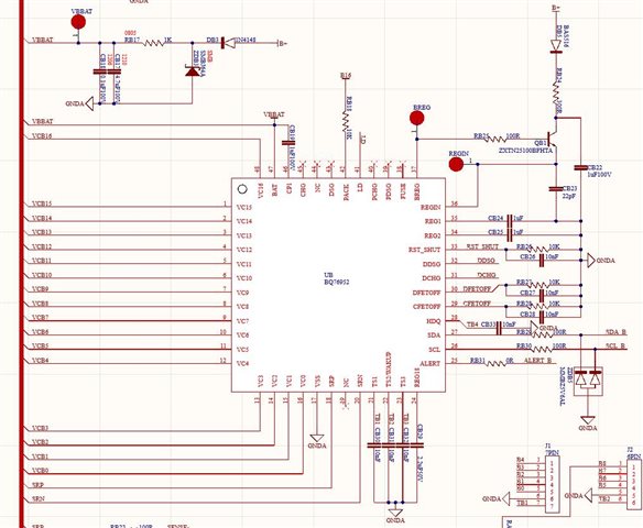
The customer test with the BQ76952 board which they designed. They use the non-contact ± 15kV to test the CAN communication port, and find 8. 9. 10 pin damage.

Total test with 8 pieces, and all of them have the same phenomenon.

How to improve this issue?

Thanks

Star

  • Hi Star,

    Are they testing with battery cells connected to the board? Pins 8,9,10 are all cell pin connections on the BQ76952 which is strange since they are testing ESD on the CAN port. I can help take a look at their schematic to see if there are any obvious issues.

    I did the testing for the BQ76952 (https://www.ti.com/lit/an/sluaa15/sluaa15.pdf ) and Ryan Tan also did testing on TIDA-010208 which is a reference design using the BQ76952. I tested voltages beyond +/- 15kV without any issue.

    Best regards,

    Matt

  • Hi Matt

    Thanks for your reply.

    Attached the BQ76952 and MOS part schematic.

    Please give some suggestions.

    Thanks

    Star

  • Hey Star,

    Matt is out of office today. He'll be able to provide some insight tomorrow.

    Thanks,
    Caleb

  • Hi Star,

    Is the testing being done with battery cells connected to the board? I didn't see an answer to this in your response. Are any of the components on the board damaged?

    I do see some issues in the schematic, although these may not be related to the ESD test failing:

    • The REGIN pin capacitor should be 22nF. It looks like it is 22pF in the image.
    • The cell input resistors (VCx pins) have a maximum resistor value of 100 Ohms. 200 Ohms is shown on the schematic.
    • The CP1 pin capacitor likely needs to be bigger (2.2uF) since there are so many FETs in parallel.
    • On our hardware, we use ESD protection capacitors between PACK+ and PACK- and across the protection FETs

    Best regards,

    Matt

  • Hi Matt

    Thanks for your reply.

    They tested with the battery cells on the board, and did not find the  components damage.

    Thanks

    Star

  • Hi Star, 

    I am not sure I understand how these specific pins were damaged, but I recommend they follow the ESD protection guidelines we use on our EVM and TIDA-010208 reference design. This application report may also be helpful: https://www.ti.com/lit/an/slua368/slua368.pdf 

    • Use capacitors across the protection FETs and between PACK+ and PACK-. Some users also use a TVS diode.
    • Use ESD protection components and spark gaps on SCL and SDA pins if they are exposed outside of the board or pack.
    • Follow the layout recommendations in the app note I linked above.

    I also recommend making the corrections to the schematic I mentioned in my last post (REGIN cap, VCx pin resistors, CP1 capacitor).

    Best regards,

    Matt