


Other Parts Discussed in Thread: UCC256302
Hello everyone,
considering power supply stabilization and power stage bode plotting the most covered situation in literatur are controllers, which feature "voltage controlled" feedback inputs: a voltage change at the feedback pin leads to an output voltage change. Nevertheless there are some controllers out there, like the UCC256302 or UCC28740, where the ammount of current change sourced from or fed into the FB pin modulates the output. Obviously for the current controlled case some considerations and modifications are necessary.
As I do not know the "usual" procedure in this case let me quickly explain how I did it for the UCC28740 and then I would kindly ask you to tell me if this is the usual way to go or where I could do better.
A typical gain/phase analyzer, as the Bode 100 in my case, requires two AC voltage signals to put into relation, so to convert the feedback current into a votage signal I chose a feedback series resitor directly connected to the FB pin (like a current shunt). The value was chosen in such a way, that on one hand the driving current source was not driven into its voltage limit due to the DC voltage drop across the resistor and on the other hand the AC signal got sufficiently large to have enough SNR. To pick up the voltage drop I used a differential probe across the resistor and connected it to channel A, respecting probe-related scaling and termination. The converter ouput voltage was fed to channel B via a standard single ended probe.
Two questions arise:
- If power stage gain shall be plotted, putting the input current in relation to the output voltage and compute 20*log(Vout / Ifb) implicates, that the units do not cancel anymore and one does not get the unitless gain. Of course it is possible to replace Ifb by the measured voltage drop across the series resistor, which leads to question 2.
- Which value of a FB "shunt" resistor can be considered as "right"? Choosing a 10k or 22k will result in random gain offsets and also random power stage crossover frequencies. Is there a standard how to face this problem?
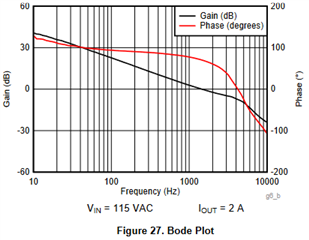
Remark to Q2: Surely you do not have to care about all this als long as you "treat" your compensator the same way. The compensator will have a voltage-to-current transfer function and you have the same situation for the output current, which has to be translated to a voltage in order to plot gain and phase. As long as you use the same shunt resistor one can easyly stabilize the closed loop. Nevertheless, the UCC28740 datasheet inclues a bode plot as Fig. 27, which is not explicitly specified as a power stage or closed loop plot, but supposed it being a PS plot, then we can extract a DC gain of 45dB. This is exactly what I get on the bench with a 10k series resistor and both probes equally scaled. Interesting 
Thanks a lot,
Felix
