This thread has been locked.

If you have a related question, please click the "Ask a related question" button in the top right corner. The newly created question will be automatically linked to this question.

BQ25570: Not correctly tracking maximum power point

Part Number: BQ25570

Dear E2E Forum,

I have some questions about an unusual behavior of the BQ25570 energy harvesting IC. I've been trying to use this IC as a supercap charger according to an article by Mr. Yogesh Ramadass, but I noticed that it isn't tracking the solar panel maximum power point properly. I've managed to narrow the issue down to the input boost charger itself. The supercap was disconnected so the buck wasn't used at all. Instead, a 50Ω potentiometer was added directly between the VSTOR pin and GND to simulate a resistive load.

Solar panel when fully illuminated (noon sun, clear sky):
Voc = 4.5V
Isc = 142 mA


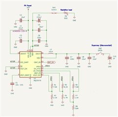
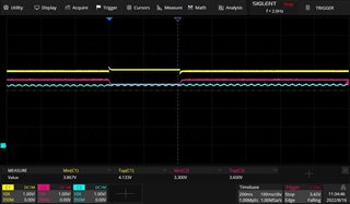
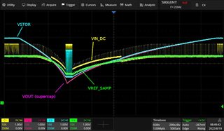
With VOC_SAMP pin connected to VSTOR according to datasheet (although I'm baffled why this pin must be connected to VSTOR rather than VIN_DC), the IC should regulate it's input voltage to 80% of the Voc (which is about 3.6V in this case). Instead, when I tested the circuit and lowered the resistance on the trimpot, the voltage on VIN_DC was at 4.1V and the circuit was drawing about 74 mA from the solar panel (303.4 mW). Voltage on VSTOR pin was a stable 3.52V, and the potentiometer was drawing about 65 mA (228.8 mW) at 75.4% efficiency. I'm not sure what's going on here i.e. why is the IC preferring this lower efficiency voltage on the input over the 80% of Voc it was programmed to.

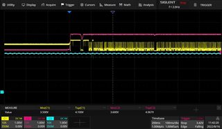
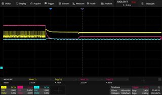
Funny thing I noticed is that whenever I disconnected the trimpot for a moment (SW1 on schematics) the input voltage (VIN_DC from PV module) would temporarily fall down to 3.5V and draw 123 mA (430.5 mW) from the PV. This was much closer to the PV maximum power point, and the power drawn is appropriately higher. Voltage on VSTOR was now 4.6V, and the dummy load drew 85 mA (391 mW) at 90.8% efficiency. This however only lasts until the clock runs out on the IC's internal 16 second MPPT timer. After a re-sampling of the Voc on the CREF cap (I see a short 230ms spike on VIN_DC on the scope) the voltage jumps back to 4.1V. The VSTOR voltage is programmed to 5V, so clearly it still has some room to boost to a higher level and draw more power from the PV panel.

Thoughts?

  • Hi Thomas,

    During the MPPT sampling when you saw the spike, what was the voltage of the spike?  Can you monitor VIN_DC on an oscilloscope and find this spike? The MPPT circuit is supposed to sample that value as the panel's VOC and then, with VSTOR=VOCSAMP, set the MPP point as 80%*VOC.  The value is stored on VREF_SAMP.  Note that VREF_SAMP might discharge a bit with a 10Megohm scope probe so you might want to use a DMM set to highest impedance (1Gohm) to monitor that voltage.

    Regards,

    Jeff 

  • Dear Mr. Jeff,

    Yes, monitoring VIN_DC with a scope shows occasional ~230ms spikes. They are about 16 seconds apart which coincides with the MPPT sampling periods on VREF_SAMP according to the datasheet. The voltage on VIN_DC was about 4.0V, but jumped to about 4.1V during the spike. Yesterday I saw a bit higher voltages on VIN_DC since we have some clouds today. Anyway, please see the attached scope pics below.

    ---

    I'm sorry, but I'm a bit confused here. Could you please explain again what voltage exactly is expected on VREF_SAMP (with VOC_SAMP connected directly to VSTOR) after a sampling period finishes?

    Is it:
    a) 100% of voltage on VIN_DC
    b) 80% of voltage on VIN_DC
    c) 100% of voltage on VSTOR
    d) 80% of voltage on VSTOR
    e) Something else?

    ---

    Discharge a bit? You mean discharge completely, right? I've already measured VREF_SAMP with a 10MΩ probe, but the cap discharged like instantly. There were occasional spikes on VREF_SAMP during the sampling periods, but the voltage disappeared as soon as the sampling was over. The DMM Hi-Z measurement was rather slow, so instead I connected the VREF_SAMP pin to an AD8641 precision opamp configured as a voltage follower and powered from a linear PSU. The output was connected to the scope (channel 3). I'm attaching some scope pictures. Sorry about the noise. I had long wires running in the lab so there's a bit of mains pickup.

    Channel 1: VIN_DC (yellow)
    Channel 2: VSTOR (pink)
    Channel 3: VREF_SAMP (cyan, via opamp)


    Picture A shows one of the spikes during operation with incorrect maximum power point. The circuit is drawing 63mA@4.1V from the PV panel (measured by two external multimeters). The trimpot load on VSTOR is drawing 55mA@3.6V.

    A


    Picture B shows captured waveforms while I momentarily disconnected the trimpot and quickly replugged it. You can see that some voltages changed. The circuit was now drawing 120mA@3.5V from the PV panel, and the trimpot is drawing 75mA@5V.

    B


    Picture C shows the resync spike - its the first sampling period after I replugged the trimpot. The system returns back to the faulty operating conditions with 63mA@4.1V in and 55mA@3.6V out.

    C

  • Hi Thomas,

    I previously missed that panel is Isc = 142 mA.  The boost charger peak inductor current is 230mA typical, which means the maximum average input current (assuming D=50% for this discontinuous mode boost converter) is 115mA.  Since your panel can provide more than this average current, the charger is not needing to find the MPP, i.e. the charger is operating at its maximum input current and providing max output power.  You can confirm this by looking at the LBOOST node and seeing that the switching pulses are very close together, i.e. no pulse skipping. 

    From your numbers above

    4.1V and the circuit was drawing about 74 mA from the solar panel (303.4 mW)

    Assuming 100% efficiency and eff=Po/pin -> 1=5V*Ivstor/ 303.4mW gives Ivstor = 60.7mA.  If we lower the efficiency estimate to 90%, then that lowers Ivstor= 54.6mA.

    Regards,

    Jeff

  • Dear Mr. Jeff,

    Thank you again for your answer. May I have one more moment of your time?

    Could you please confirm, if this behavior is in fact a current limitation on LBOOST? Because I'm baffled by the numbers. Running the PV at 4.1V and 74 mA gives 303.4 mW which is a far cry from the 510 mW maximum advertised by the datasheet. And the IC is apparently capable of running under higher power under some conditions.

    I made an interesting picture where I have a 15F 5.5V supercap attached to the buck VOUT pin. It's basically the same schematics from my first post, but without the dummy resistive load on VSTOR. The image shows a timelapse of voltage curves for VIN_DC, VSTOR and Vsupercap during a discharge and a recharge of the supercap.


    Observations:
    - The BQ25570 seems to be switching between a "low-power" and a "high-power" mode during discharge and recharge.
    - The "high-power" mode appears on the voltage edges while the "low-power" mode appears in-between (between 2V and 4V on VSTOR).
    - The "needles" on VIN_DC (yellow curve) where the VREF_SAMP sampling is taking place never reach the full Voc voltage (4.5V) of the solar panel in the "low-power" mode, but seem to follow slightly above the curve.


    Could you confirm, if this is a normal behavior of this IC? If so, I will mark this thread as solved.

  • Hi Thomas,

    That is not normal behavior unless LO POWER is referring to the output voltage of your solar panel.  I don't understand why VIN_DC is is stead during HI POWER then jumps up and then follows VSTOR down, then jumps back up.  VIN_DC should "regulate" to 80% of VOC.  Can you try with a current limited power supply or power supply with series resistor?

    Regards,

    Jeff

  • Dear Mr. Jeff,

    Thank you for the answer. The LO-POWER phrase refers to the segments when the 'incorrect' MPP tracking is present. VIN_DC was connected to the PV panel, so technically the voltages should be the same.

    I have repeated the test as you suggested. The solar panel was replaced with a PSU @ 4.5V and about a 20R resistor in series. The current draw was about 65mA maximum when the supercap voltages were at its lowest. I've included VREF_SAMP (green curve) in this measurement - curiously enough it does not seem affected by the sudden voltage changes on VIN_DC rail.

    Pulse skipping on the LBOOST node appears present only when the BQ25570 is in "high-power" mode, but disappears (pulses are spaced evenly apart) when the yellow line is elevated.

    EDIT: Followup question.

    This IC has a VREF_SAMP sampling period every 16 seconds or so... How much current is supposed to flow into the IC while the sampling is taking place? I've measured the input current in high resolution, and it seems that the input current momentarily drops from 50 mA to 25 mA (not 0 mA) during sampling, which likely causes the noticeable voltage drop on VIN_DC.

  • Hi Thomas,

    When the sampling takes place, the expectation is that very little current flows.  There is a path from VIN_DC through the inductor and the high side PFET body diode to VSTOR so if VIN_DC>VSTOR+0.6V, current will flow from VIN_DC to VSTOR.  But, with a high Z source, this usually isn't a problem.  Since your panel has high Voc and Isc, I suspect you are getting current flow that is collapsing VIN_DC. The only way to prevent that would be turn off the load on VSTOR whenever VSTOR<VSTOR+0.6V using VBAT_OK signal.  The buck converter automatically stops switching if its input, VSTOR, drops close to VOUT.

    Regards,

    Jeff

  • Dear Mr. Jeff,

    Yes, I came to the same conclusion after reviewing the BQ25570 datasheet. The issue becomes less noticeable when using a weaker solar cell. That's too bad though, I was hoping to squeeze a bit more juice out of this IC. Anyway, thanks for your time. I guess I'll mark the thread as solved for now despite the fact I wasn't able to get an ideal solution. I will reevaluate my circuit design.

    Best regards,

    Thomas