This thread has been locked.

If you have a related question, please click the "Ask a related question" button in the top right corner. The newly created question will be automatically linked to this question.

LP55231: LP55231: Engine not trigger

Part Number: LP55231

Hi, 
I am facing issue with LP55231 Engine start and trigger in CC1312. 

I follow this Library(https://github.com/sparkfun/SparkFun_LP55231_Arduino_Library).

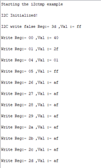
I can write register value successfully. but engine not working.

For trigger i am using gpio11( every 2 second gpio11 high/low).

  • Hi,

    I've seen your problem, and I have some questions for you:

    1.In the Github link, I find there are 10 examples and I don't know which one is confusing you.

    2.LP55231 has three independent program execution engines, I don't  know if you can't use this function or you can't start the LP55231 device.

    Besides, there are some suggestions for you:

    1.You can check the LP55231 datasheet on ti.com, make sure relative registers are properly configured.

    2.We also provide relevant software about   LP55231, you can use this as a reference.

    3.If you want to evaluate the performance of the chip, I sincerely recommand you to use the official EVM.

    Thanks,

    Best Regards.

    Ives, Li

  • Hi, 
    Thanks for the response.


    1) I follow this example (https://github.com/sparkfun/SparkFun_LP55231_Arduino_Library/blob/master/examples/engines-output-trigger/engines-output-trigger.ino)

    Steps as per the above example:-


    1) Reset WriteReg(0x3D, 0xff);
    2) Enable WriteReg(0x00, 0x40 );
    3) REG_MISC WriteReg(0x36,0x53);
    4) SetLogBrightness For all channel
    5) SetDriveCurrent for all channel and value 0x6F/0x7F


    For Load program:-
    1)
    WriteReg(REG_CNTRL1, 0x00);
    WriteReg(REG_CNTRL1, 0x15);

    For running Engine:-

    1)
    SetEngineEntryPoint(0, 0);
    SetEnginePC(0, 0);
    2)
    SetEngineModeFree(0);
    SetEngineRunning(0);

    And every 2 seconds GPIO11 set/reset for trigger signal of LP55231

  • Hi,

    Can you share your mail id? i can share my source file.

  • Hi,

    I notice that you set CNTRL1 register to 0x15, which means you don't enable the chip, you can try to change the value of CNTRL1 to 0x55.

    If it doesn't work, you can contact my e-mail: ives-li@ti.com. 

  • HI,
    I sent mail on  this mail id:- ives-li@ti.com.
    Please check your mail

  • Hi,

    Because of the NDA restriction, I can not receive your source file.

    I'm sorry about that.

  • Hi,

    which way to share file?

  • I think I can not receive your file, and I am a hardware engineer, which means I may not have the power to check your code.

    But I think if you need, I can explain how to use our product and you can follow the guidance to find which step is wrong..

  • Thanks for the responce.

    i will be very glad you guide me how to drive led driver.

  • Hi,

    I will show you the register you need to configure down blow:

    (00) ENABLE/ENGINE CNTRL: enable the device and choose the engine execution mode.

    (01)ENGINE CNTRL2: use this register to Load or Run your program.

    (04/05)OUTPUT ON/OFF: control on/off for D1-D9 output

    (36)INT_CLK_EN: select the clock source, we need 32.7kHZ for correct operation.

    (3A)STATUS/INTERRUPT: configure the interrupt for engines.

    (4C/4D/4E)ENG PROG START ADDR: It is the start address for each engine program.

    (4F)PROG MEM PAGE SELECT: use to select your program memory page, I will show your more details on blow photo.

    (70H/75H) ENG MAPPING: you can read the mapping information from here.

    Please check these registers.

    Thanks!

  • Thanks for the reply, but still not working.

    Write register and their value listed below,

    Register value
    00           60 //enable and engine 1 enable
    36           01 //int_clk_en
    01           20 //engine 1 load program mode
    04           01 //d9 output mode
    05           ff //d1-d8 output mode

    Loadprogram (pattern,16)

    4c           00 //ENG1 PROG START ADDR
    4f            01 //page select 1
    70           01 //ENG1 MAPPING MSB
    71           ff // ENG1 MAPPING LSB

    3A           02 //STATUS/INT

  • Hi,

    I notice that you set 01ENGINE CHONTROL2 to 20, which means bit[5:4] is 10.

    I think at first you should set the bits to 01 to load your program, after that, change the bits to 10 to run your program.

    Besides, ENG1 MAPPING is a READ ONLY register, you can only read the situation of each output.

    If you want to configure the engine or select the outputs you need, please use the LED Driver Instructions(Table 4) and LED Mapping Instructions(Table 5).

    If you want to trigger your device ,you can find the trigger instruction in Branch Instructions(Table 6).

    You can also find the description of each instruction in the datasheet.

    Thanks.

  • Hi,
    Stil not working,
    Register           Value
    0x3D                 0xff
    0x00                 0x40
    0x36                0x53

    0x4f                 0x00 // page 0 is selcet for write value
    0x4c                0x00 // 00 //ENG1 PROG START ADDR

    0x3A               0x10 // clear engine register
    0x01               0x10 // engine 1 in load program mode
    0x04               0x01 // D9 led output mode
    0x05               0xff // D1-D8 led output mode

    0x50               0x9d // write data 50h
    0x51               0xf0 // write data 51h

    0x01               0x20 // engine 1 in run program mode
    0x00               0x60 // ENGINE1_EXEC 1 in run program mode
    0x37               0x00 // ENGINE1_EXEC 1 in run program mode

  • Hi,

    One thing I find In your code is that the PROG START ADDR should be 50.

    Besides, you write just one instruction, but you haven't selected the output you want to choose by the mux_sel instructin.

  • Hi,

    Here is an example to let the LED blink:

    00H   0100 0000

    01H   0010 1111

    04H   0000 0001

    05H   1111 1111

    26H-2EH   10101111

    36H   0101 0001

    37H   0000 0010

    4CH   0000 0000

    4DH   0100 1111

    4EH   0101 1111

    41H   1000 1111

    42H   0011 0010

    4FH   0000 0000

    Program memory:

    00   9D03                         mux_sel    3

    01   40FF                         set_pwm   FFh

    02   5E00                         wait 0.24

    03   4000                          set_pwm   00h

    04   5E00

    05   A001                         branch  0,   loop1

    06   C000                         end

    Program function: 

    Select LED3, In this loop, pwm will be set to 0% or 100% every 0.24 seconds.

  • Registers value:

    00 55
    01 2A
    02 00
    03 00
    04 01
    05 FF
    06 00
    07 00
    08 00
    09 00
    0A 00
    0B 00
    0C 00
    0D 00
    0E 00
    16 00
    17 00
    18 00
    19 00
    1A 00
    1B 00
    1C 00
    1D 00
    1E 00
    26 AF
    27 AF
    28 AF
    29 AF
    2A AF
    2B AF
    2C AF
    2D AF
    2E AF
    36 51
    37 02
    38 00
    39 00
    3A 00
    3B 00
    3C 00
    3D 00
    3E 00
    3F 19
    40 00
    41 8F
    42 32
    45 00
    46 00
    47 00
    48 00
    49 00
    4A 00
    4C 00
    4D 10
    4E 20
    4F 05
    70 00
    71 04
    72 00
    73 00
    74 00
    75 00
    76 00

  • Hi lves Li,

    I compared ESP32 and CC1312 lauchpad with LP55231 sparkfun board. I found one thing. CC1312 can't reset. i.e. on reset(0x3d register) value is not set 0xff. other register can write/read sucessfully.

    On Esp32 reset value write suceffuly. 

    in CC1312 and LP55231, only (0x3d-->0xff) write failed. 


  • So what can I help you?

  • Hi,

    Is their any solution available for write failed on 0x3d register?
    I think, that is maybe one of the reasons of engine not trigger.

  • Could ESP32 write 0x3d register?

  • yes, I checked.
    0x3d ---> 0xff write successfully.

  • So it is cause by your CC1312 code.

    But I'm sorry  I can't  solve your software problem.

  • Only this register 0x3d-->0xff value write failed.
    other register and value write successfully

  • I understand