This thread has been locked.

If you have a related question, please click the "Ask a related question" button in the top right corner. The newly created question will be automatically linked to this question.

LM3405A: When dimming, how can I solve the problem of high frequency sound?

Part Number: LM3405A
Other Parts Discussed in Thread: LM3405

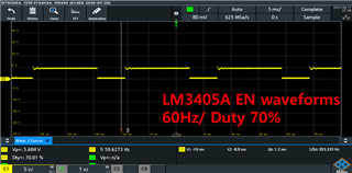
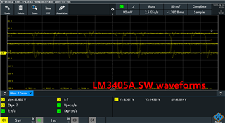
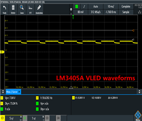
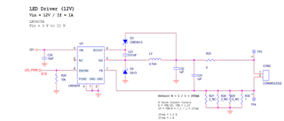
LED PWM control is being carried out using LM3405A.

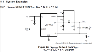
Designed to be the same as the application notes in the datasheet.
The diodes are the same, and for C the internal voltage is slightly higher.

Currently, the duty is periodically adjusted using a frequency of 120 Hz, and at this time, high-frequency sound is mainly generated.

What improvements should be made to prevent high frequency sound? (You must use 120 Hz unconditionally.) 

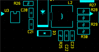
And Board A and Board B are designed to have the same LED driver ends, but the output currents of A and B differ by about 10mA.

I don't know why. The only difference is the LM3405A package difference and the number of parallel resistances. Board A used SOT23, two parallel resistors, and one was NC-treated.

Board B used four HVSSOP parallel resistors, and three resistors were NC-treated. I don't know why the current is decreasing...

Do I have to use only one current control resistor?

  • hi Kim

    to go deep into "high frequency sound", pls help provide waveforms of SW, VLED(TP3), inductor current, EN. Besides, what is LED string voltage? 

    Do Board A and B keep the totally same layout except IC package? what are the exact current values of A and B, which one is exactly regulated at 200mA?  A with two 2R resistor in parallel and B with one 1R resistor?

  • Hi, Wang. 

    Thank you for your quick reply.

    First, boards A and B have different layouts.

    I think it is difficult to compare equally because current measurements can vary due to different factors.

    Thank you for your interest in the question.

    I have attached SW, VLED, and EN waveforms. Inductor current has not yet been measured.

    The inductor used the same SLF6028T-4R7M1R6 (4.7 μH, 1.6 A) as the BOM in the datasheet.

    The LED bar connected to the driver has the following specifications. (Diode On 3.7V, two serial connections)

    What part should I check? Also, I'm attaching the measurement waveform, so please check it.

    Thank you.

    Dayoung

  • hi Kim

    SW waveforms seems not adjusted to be stable, you can try to adjust trigger line to make the waveform stable.

    Normally, high frequency sound can be from oscillation of inductor current and thus better to get inductor current waveform.

    At the same time, any difference if increase dimming frequency from 120Hz to like 1kHz? 

  • hi, Wang
    Currently, it is difficult to measure inductor current waveform because there is no current probe.
    Is there any other way to do it?

    I will check the SW waveform again by adjusting the trigger line.

    The same is true when the frequency is changed to 1 kHz.
    However, there is no sound when the duty is set to 100%.
    If it is changed to 70% and 50%~ 10%..., it continues to appear.

  • hi Kim

    One thing I just noticed is that for this circuit that Vboost derived from Vout, the voltage between SW and Boost should be within 2.5V-5.5V. However, from your waveform Vout=~7V and forward voltage of D3=0.8V max, the value may beyond this range. You can try to decrease Vout and see if this helps.

  • hi, Wang.

    I appreciate your prompt reply.

    When the initial Vin=12V, Vboost=13.5V and Vsw=6.6V were confirmed.

    If you connect two serial LEDs, VLED (TP3) = 6.3 V.

    When Vin=5V, Vboost=6.9V and Vsw=3.3V were confirmed.

    If you connect one LEDs, VLED (TP3) = 3.2 V.

    But, The same sound was heard when Vin=5V.

    I was wondering if it was a problem with D3 and C23, so I opened it individually, but I checked that the sound was the same.

    Please let me know what else I should check.

    Thanks. 

  • hi kim

    Does Vboost and Vsw mean voltages of Boost pin and SW pin? why Vboost has higher voltage than Vin? you can provide waveforms if available. 

    Besides, after you checking voltage stress between SW and Boost is not a problem, as inductor current is not available, then pls try to increase C22 and C23 to 4.7uF.

  • hi kim

    I would like to resolve this thread if this has been resolved at your side. thanks

  • hi Wang.

    I'm sorry for the late response.

    It was confirmed that the sound was generated because it was not peaceful.

    I added a capacitor and checked that there is no sound.

    Thank you for your advice on many ways.

    Thank you again for everything you've done! 

  • hi kim

    Glad to hear that. Would you mind my asking the application here for LM3405 and why this is chosen? Does the reason is that this can support Vin down to 3V?