This thread has been locked.

If you have a related question, please click the "Ask a related question" button in the top right corner. The newly created question will be automatically linked to this question.

TPS65988EVM: Firmware and dead battery configuration

Part Number: TPS65988EVM

Hello,

TPS65988 will be connected over I2C to a MCU. Port A if for connecting to a power adapter and Port B is for a device that needs communication and charging,

External flash purpose: In the datasheet is written that the external flash is optional, but seems it is not. I am not sure did I understand it, but correct me, please, if needed. This device has a built-in firmware, but it requires external flash to be uploaded a new up-to date firmware in case TI finds some issues? The flash is needed and for storing settings, TPS65988 to be able to work in a stand alone mode? Can you give a list of flash ICs that are supported? So in every flash is always needed to be written the generated bin, by the MCU over I2C through TPS65988 over SPI when the device is started for a first time?

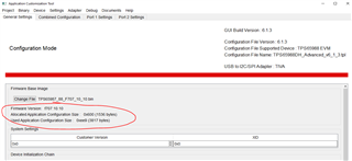
BIN FILES: I tried to save bin file from the GUI, but I got an error: The size of the app config data table generated by this project (0xee9 bytes) is larger than the allocated region supported by the firmware image (0x600 bytes). Save operation has been aborted.

Dead battery: here my EVM get damaged  and I wasn't able to finish the experiments, but... I want the TPS65988 to be able to activate just 5V of the adapter (not the maximum available as it happens up to now). If I want to be used default Configuration 2: ( UFP only (Internal Switch) 5 V at 0.9 - 3.0 A Sink capability), is needed to have a divider ratio at ADCIN1 around 0.25 and 0V at SPI_POCI. But if I connect SPI_POCI (MISO) to ground the external flash will not operate.

  • HI Ivaylo,

    This device has a built-in firmware, but it requires external flash to be uploaded a new up-to date firmware in case TI finds some issues?

    Yes that is correct.

    The flash is needed and for storing settings, TPS65988 to be able to work in a stand alone mode?

    Once you flash the PD controller once with your configurations, it will keep those settings until you flash them again. 

    So in every flash is always needed to be written the generated bin, by the MCU over I2C through TPS65988 over SPI when the device is started for a first time?

    Yes that is correct.

    For the BIN files problem, can you send your PJT file from the GUI so I can try to recreate it from my end? 

    Regards,

    Raymond Lin

  • Dear  Raymond,

    Thank you for your reply!
    As I don't have your e-mail I will ask Vsevolod to send it to you. It is not a final configuration, just a test one. Can you check why is oversized, I to be able to fix it by myself and don't bother you in future for that? 
    In general the bin file is created in the GUI from the configuration. So in future we need to check is there a newer version of the GUI and like that the firmware to be up to date. Correct?
    Do you happen to have a library in C for loading of the firmware to the external flash? I suppose that it will be easier and faster for the programmer.

  • Hi Ivaylo,

    It seems like there is a bug with exporting the settings as JSON file. This issue is being addressed and will be fixed in the next version of the GUI (version 6.1.4). For now, I recommend saving your configurations as a PJT file instead by clicking on Project->Save Project and then choose the file location and name as shown below: 

    You can load a PJT file onto the GUI and you'll be able to access all setting configurations. I will send Vsevolod an example PJT file with your configuration settings copied onto it. If your current project (from your end) shows on the General Settings page the Used Application size is much greater than the Allocated size, you'll need to create a new project (the JSON setting probably corrupted something in your project). Example of corruption is shown below:


    Avoid using JSON settings until the next GUI version is released. If you have any further questions or concerns, please let us know!

    Thanks and Regards,

    Raymond Lin

  • Hello Raymond,

    Thank you for the information! Now there is no problem with the configuration size. I am able to send to the flash and the new created bin. But here comes one more question. Despite that I wrote the configuration to the flash, if I restart the power supply of the EVM, I need to export settings to device RAM. Why?

  • Hi Ivaylo,

    Once the EVM is flashed, it should contain the configuration that you flashed previously until you re-flash it again (no need to constantly reflash). After you power-cycle the EVM, is it not displaying the proper configurations?

    Regards,

    Raymond Lin

  • Dear Raymond,

    The configuration that needs to be in the flash doesn't start.
    There is something strange. If I Flash from current project and after that I do Flash Read, both files are different - added a lot of 0xFFs and few different bytes.
    If I Save a binary and do Flash from binary file, after that I do Flash Read - the difference in the two files is a big offsets with 0xFF somewhere  in the middle of the file. There is a couple of dialogues that asks for entering offsets (which exactly should be they). There is a even a place to determine it automatically, but doesn't work - error missing dll file.

  • Hi Ivaylo,

    After you flashed your device, did you power cycle your device (turn off and turn on again)? The PD won't load your new configuration unless this procedure is done. 

    If you did follow this procedure, I'm curious as to how did you compared the files and can you point out the difference(s)? It's normal to see some 0xFF (built in for padding purposes). Also when you're saving a flash, make sure you're saving the Full Flash and using that bin file to program the PD controller. 

    Regards,

    Raymond Lin

  • Hi Raymond,

    Yes, I power it up again. Like  that I test does it load the new configuration from the flash. I use Beyond Compare 4 software. Yes, I save the full flash. 

    Why when I give flash from current project the default offsets are 0x2000 and 0x20000 (not possible to determine it Exception Encountered during I2C region read:Error importing aardvark.dll

    Architecture of aardvark.dll may be wrong

    No module named aardvark

    DLL load failed: Le module spécifié est introuvable.

    <type 'exceptions.ImportError'>)

    and when I press save binary the default offsets are 0x2000 and 0x7000? 

  • Just to add some details/example.

    I give a command Export settings to device RAM - the EVM starts to work according to the set configuration. After that - flash from current project and after the successful message I press the reset button of the EVM and the EVM doesn't start with the same working for me configuration. 

  • Hi Raymond,

    In slvae21a.pdf is written

    "When the initial device configuration is complete, the boot code samples the BUSPOWERZ pin to
    determine the start-up behavior of the device. The device can operate with or without an external flash.
    On the systems where the external flash is not available, the code patch and device configuration is
    downloaded to the SRAM of the device from the external host over I2C or internal ROM, depending on
    the BUSPOWERZ configuration."

    The external flash takes space and money. Even seems that in my all tests it's not used at all.
    Can you give me algorithm how the code patch to be loaded over I2C directly to the SRAM?

  • Hi Ivaylo,

    In that same document (https://www.ti.com/lit/an/slvae21a/slvae21a.pdf?ts=1661309026969&ref_url=https%253A%252F%252Fwww.ti.com%252Fproduct%252FTPS65988) starting on page 7 there is an example (sudo) code on the process of the flash update execution. WE don't have any specific algorithm on hand since this depends on the EC/MCU that's in used. 

    Regarding the default offsets and different settings to configure the EVM, let me confirm with my team if this is proper behavior of the PD.

    I'll get back to you as soon as possible!

    Thanks and Regards,

    Raymond Lin

  • TPS65988_portB-Adapter_7.pjt

    Hi Raymond,

    I decided to switch the places of the adapter and the device. Of course I changed the configurations. Adapter at port B. The strange thing is that the settings for Transmit Sink Capabilities in the GUI for port 1 controls the adapter which is at port 2 connected and Sink Capabilities for port 2 in the GUI doesn't influence the work of the adapter. Are you sure that there is no newer version of the GUI already??

  • Hi Ivaylo,

    The difference between the files you observed (0xFF and few different bytes) are not behavioral difference, they are just there for padding. 

    Once there is a newer version of the GUI, it'll be released on the TI website and your FAE can notify you about it. I'll take a look at your pjt file and let you know any updates via email.

    Thanks and Regards,

    Raymond Lin

  • Dear Raymond,

    Thank you for your replies!
    I put a USB analyzer at the I2C bus. Only the registers are send first at address 0x20 and after that at address 0x24. The patch is not sent over the I2C, so seems like that the flash is really needed. I've exported the bin files as *.c and found out that all registers are mentioned twice, i.e. for both ports. Here comes the question why if all registers are really set in the firmware (bin) why they are not loaded automatically after the device reset? Is it possible that really there is a problem with the values of the offsets?

  • ...and seems that the patch it is loaded, because if I unsolder the flash the system absolutely doesn't  start to work correctly after exporting settings to device RAM . So why just the patch is loaded, but not and the register sets?

  • Hi Ivaylo,

    Let me consult with my team and get back to you tomorrow.

    Regards,

    Raymond Lin

  • Dear Raymond,

    I will be waiting for this answer.

    I want to share more information. I verified I2C captures with an analyzation. What I found out is that when loading the settings to device RAM registers 0x28, 0x32, 0x33 are loaded with the same values at address 0x20 and 0x24 (I suppose and for the rest is the same, but didn't check). And they are loaded with the values for PORTA (I compare the data with the RAW view in the GUI). From here should come a lot of problems. The other thing is that register 0x5C is not loaded at all. In the generated c file (bin) the registers are the same again, but 0x5C is included.

  • Hi Ivaylo,

    Thank you for the update, once I compile my findings I'll let you know.

    Best Regards,

    Raymond Lin