This thread has been locked.

If you have a related question, please click the "Ask a related question" button in the top right corner. The newly created question will be automatically linked to this question.

TPS61165 - not working

Other Parts Discussed in Thread: TPS61165, TPS63001, TPS63000


Hi,

I am having issues with TPS61165 and they are
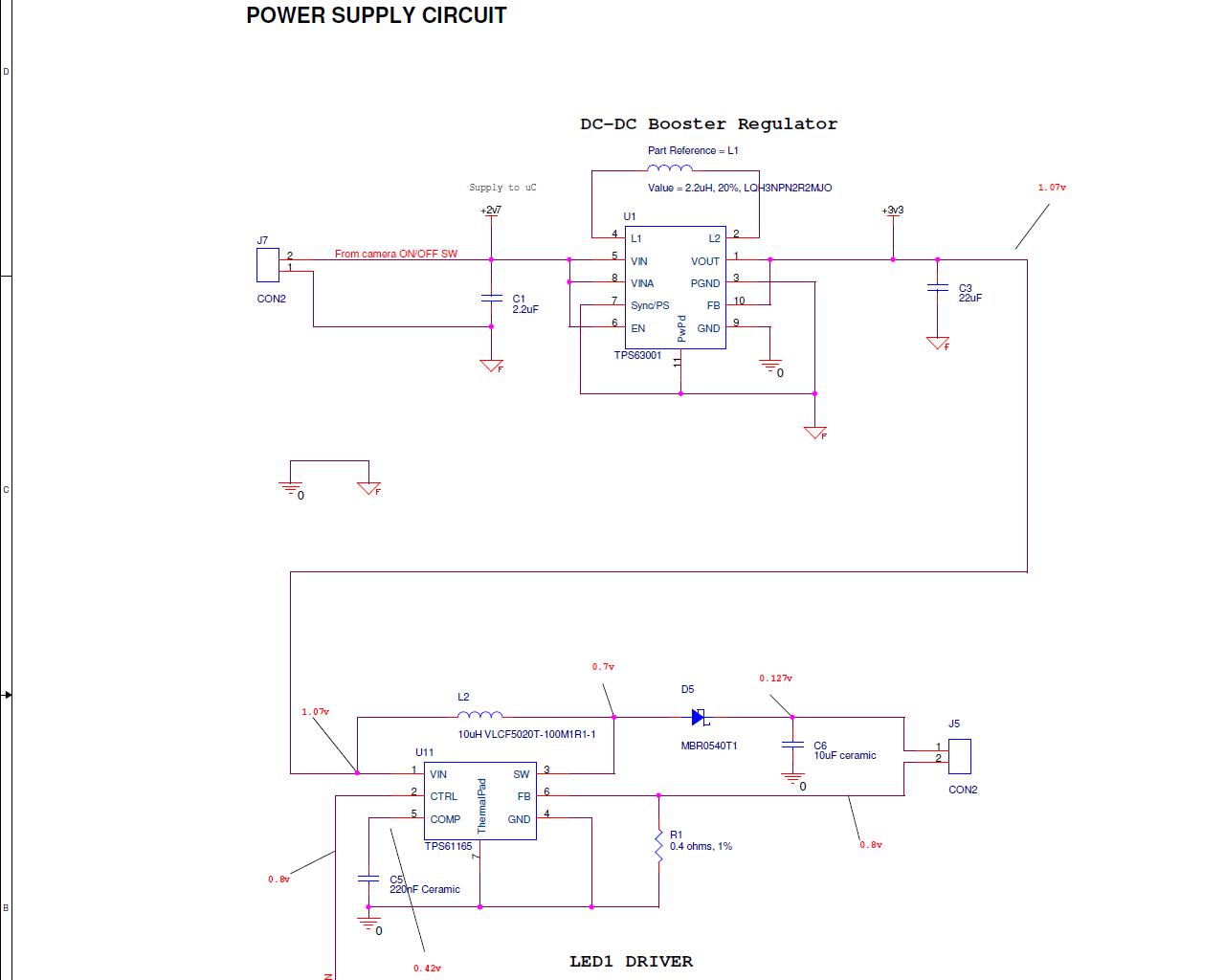
1. w/o 10uH inductor, TPS63001 booster gives out 3.3v as expected.
2. With 10uH inductor, the booster o/p reduces to 1.07v and not getting expected working from LED driver.

In both the above cases, connecting  the 3W LED at the driver o/p is not helping the cause.

I have marked the voltages at TPS61165 nodes in BOLD RED texts with arrow.

Trying to drive a 3W LED.

Appreciate any help.


Attached is the image of the circuit.


Thanks,

Karthik


  • There are several things that could be wrong, so this will require some debugging on your part.

    First, the TPS63001 requires at least 4.7uF of input capacitance.  I would recommend adding a 22uF input cap and seeing if that helps.

    What is the current limit of your 2.7V input supply?

    Can you try powering the TPS61165 directly from a lab power supply and not through the TPS63001?

    The voltage on CTRL (pin 2) is 0.8V.  This is between the logic high and low levels.  What is this pin connected to?  Can you send a scope capture of what it looks like?

    Yes, you will need to attach the LED for the circuit to work properly.

  • Thanks chris.


    I have tried supplying directly from power supply regulator bypassing tps63001.

    Still there is no positives.

    Current limit of power supply is >3A.

    The CTRL pin is connected directly to Vin of tps61165.

    I have tried with LEd present at the load. But no positives.


    Regards,

    Karthik

  • Is the circuit on a custom PCB or are you using two of TI's EVMs?  If a custom PCB, then my question is did you manually solder the TPS61165 and/or its passive and active components onto the PCB?  If so then is very positive that the IC was damaged during soldering.  These 2x2 QFN packages will expand when heated assymetrically (i.e. soldering only one pin) and this can cause either the wire bond or the die itself to crack.  If you do not have access to a heat gun or solder reflow oven, you can attempt to solder the IC and components on a hot plate so that the thermal differential is lower.

  • Thanks Jeff.


    I am hand-soldering the IC in custom made PCB and not the evaluation board.

    Will the 10uH inductor value be of any issue ?

    I chose this value so that the device gives out 900mA load current.


    Regards,

    Karthik

  • The TPS61165 has a current limit slightly below 1A.  Being a boost converter, it will never be able to provide output currents near its current limit.  Please use datasheet equation 4 on page 14 to determine how much output current the TPS61165 can provide given your minimum input voltage, maximum output voltage and efficiency estimate of around 90%.

  • Thanks Jeff,

    Thought it cannot provide 900mA, it should not pull-down the input voltage right ?
    When given input of 3v, the tps61165  pulls it down to 1v consuming ~2.5A.
    Could you let me know what state the IC is now ?
    Will this scenario occur only if IC got damaged ?


    Regards,
    Karthik

  • The TPS61165 should only be trying to pull current up to its maximum limit of 1.44A.  Can the rail supplying power provide that much?  If not, then it will be pulled down.  If you broke the connection between the TPS63000 and the TPS61165 and tried powering the TPS61165 from a power supply and did not see switching at the SW pin and/or the SW pin rise above the input voltage, then the TPS61165 is damaged.

    Also, I didn't see an input capacitor close to the TPS61165 between VIN and GND on your schematic.  That is recommended.

  • Thanks Jeff.


    We tried hot-air gun soldering and the system worked good.

    Thanks a lot for your prompt help.


    Regards,

    Karthik

  • Hi,


    I am encountering a new issue w.r.t tps61165.

    When I make the CTRL pin of tps61165  zero, the ckt shuts down but the LED connected to the load still glows.

    I guess the LED draws current through the inductor of tps61165.

    How can I make the LED go OFF in this situation.

    The tps61165 gets fixed 3.3v as input.


    I tried having two 3W LEDs in series at the load but it didnt help as tps61165 max o/p is 3.3v & the combined forward voltage of 2 series LEDs = ~5v.

    But in the tps61165 datasheet it is shown that 3 OSRAM LEDs(LW-W5sm = min. forward voltage=2.7v) can be connected at load.

    Can you help me on this.


    Regards,

    Karthik

  • Hi,


    Is there a way to boost the tps61165 output such that it gives out enough voltage to drive two LEDs in series having forward voltage = 2.9v each ?

    When I see the plots given in tps61165 datasheet, there is efficiency vs output current plot that shows 12v VOUT for 5v VIN. How the boosting is happening here ?


    Regards,

    Karthik

  • If connected per the datasheet and if the sum of the forward voltage drops of the WLEDs connected on the output are higher than the input voltage, then the boost converter will boost the output voltage only high enough to provide the LED current programmed by the resistor from the FB pin to ground.  If the circuit is not working, then it is either connected improperly or the IC is still damaged.