This thread has been locked.

If you have a related question, please click the "Ask a related question" button in the top right corner. The newly created question will be automatically linked to this question.

BQ2031: DV2031S2 Demo Board Schematic Question

Part Number: BQ2031

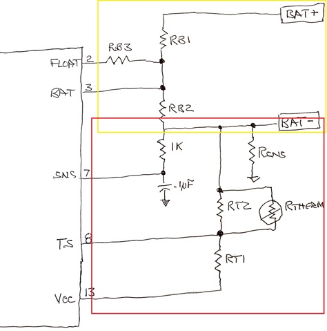
In the schematic shown in the "DV2031S2 Lead-Acid Charger Development System" (Rev B board) datasheet, there is a resistor R18 (1K Ohm).

This resistor appears to be in series with RB2 as defined by Figure 6 "Configuring the Battery Divider" of the BQ2031 datasheet (June 1999 E).

This same resistor also appears to be in series with RT2 as defined by Figure 8 "Configuring Temperature Sensing" of the BQ2031 datasheet (June 1999 E).


Its presence affects both the Battery Divider and Temperature calculations.

Question: Why is this resistor there? 

Thank you.

  • Hello

    R18 along with C13 will form a filter for the Current Sense Pin.

  • Thanks, Bill, for your quick reply.

    So, if I understand correctly, RB1, RB2, and RB3 simply have to do with the voltage across the battery (shown in yellow in the picture above). Pin 7 (SNS) has no effect on their calculations.

    Pin 7 (SNS) measures the voltage on the sense resistor (Rsns). Since the input impedance of the SNS pin is a minimum of 50M Ohm, the 1K resistor doesn't come into play. Thus, the 1K and .1uF simply smooths out the voltage on the SNS pin.

    I know this is an old datasheet, but I couldn't find any reference as to why someone thought the filter was needed.

    BTW - Makes me appreciate the current datasheets TI provides!!