This thread has been locked.

If you have a related question, please click the "Ask a related question" button in the top right corner. The newly created question will be automatically linked to this question.

TPS25750: USB-PD-CHG-EVM-01

Part Number: TPS25750
Other Parts Discussed in Thread: USB-PD-CHG-EVM-01, , USB2ANY, BQ25792

Hi TI Support Teams,


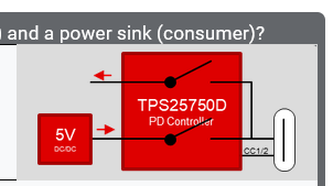
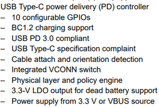
I am evaluating the TPS25750 PD controller for our battery charger design. I would consider TI's USB-PD-CHG-EVM-01 is the good candidate to start the evaluation. My evaluation steps will be:

1. To use the USB-PD-CHG-EVM-01 as a USB PD power sink to charge our product battery.

2. To use the TPS25750 Application programming Tool to configure the TPS25750 and generate the binary file to program the EEPROM.

3. To interface the TPS25750 slave I2C port to a MCU.

According to the USB-PD-CHG-EVM-01 web page, I have purchased both USB-PD-CHG-EVM-01 and USB2ANY HW.. I have the following questions I would like to confirm with TI teams:

a) Is the TPS25750 application programming tool compatible with the USB-PD-CHG-EVM-01 and USB2ANY HW since I would like to use the TPS25750 application programming tool to change the TPS25750 configuration on the USB-PD-CHG-EVM-01 with different PD voltage or current? If not, what is the HW setup which allow me to configure (not program) the TPS25750 and generate a configuration binary file for EEPROM?

b) What is the USB2ANY for if the answer to the a) question is negative since connector J3 on the USB-PD-CHG-EVM-01 is marked for USB2ANY?

Thank you,

HLi

  • Hi Hang,

    Let me check with our team regarding this and I will get back to you by tomorrow!

    Thanks and Regards,

    Raymond  Lin

  • 1. You can use any 24C EEPROM programmer (i.e Aardvark) with the Aardvark connector on the EVM to flash the TPS25750 with a generated binary file from the GUI. The GUI stores the binary file in a Intel hex format, which is compatible with many 24C EEPROM. The USB2ANY is not compatible with our GUI.

    2. USB2ANY connector was included with the intention of adding a driver to support USB2ANY, however the driver is not completed nor is it scheduled to be completed anytime soon.  I apologize for the inconvenience this brings.

    Please let me know if you have any further questions, comments, or concerns. 

    Thanks and Regards,

    Raymond Lin

  • Hi Raymond,

    Thank you for the reply.  As you suggested from answer 1,  I am using the Aardvark I2C/SPI adapter from Total Phase and downloaded their Flash Center tool to access the EEPROM (CAT24C256) on the USB-PD-CHG-EVM-01 board.  Using this setup, I was able to read the on-board default EEPROM configuration binary file and saved it just in case I can restore the EVM back to the factory default.  I plan to use the TPS25750 Application Customization GUI tool to create a new configuration for the TPS25750 I am evaluating. I have two questions to ask:

    1. Since the USB2ANY is not compatible with the TPS25750 Application Customization Tool in HW, therefore, No hardware is connected the Application Customization Tool.  I would like to confirm that Application Customization Tool is still able to generate a new configuration binary file for me to program the EEPROM via Aardvark adapter.

    2. To create a new configuration binary ( I am afraid I may need to convert to the intel hex file you mentioned) file, I made all 13 selections on the application customization tool based on my new configuration.  I selected "Generate low region binary" option (what is the difference if I choose " Generate full flash binary"?) and "binary" file format before I clicked "download"tab.

    If both steps above are correct, then I should be able to get a new configuration .bin file to download it to the EEPROM on the USB-PD-CHG-EVM-01 board.

    Please let me know if you see if I have missed something, or overlooked some details or steps in between.

    Thank you,

    -Hang

  • Hi Hang,

    1. You can still use the online Application Customization Tool (version 7.0.3) to generate a working binary file to flash the evm. You would need to generate a full-flash binary file, which you would then need to upload onto Flash Center. 

    2. As mentioned in the previous answer, generate a full-flash binary file and upload it to the Flash Center. You can then flash the EVM using Aardvark and the binary configuration should then be loaded onto the evm. The TPS25750 requires a full-flash binary (which contains a high-region and low-region) binary configuration.

    I would also like to make a note that currently there is a bug in the online GUI that causes some issue with I2C communication with the BQ25792. More information regarding this bug can be found on this FAQ: https://e2e.ti.com/support/power-management-group/power-management/f/power-management-forum/1133736/faq-when-i-configured-the-usb-pd-chg-evm-01-using-the-online-application-customization-tool-the-pd-controller-isn-t-communicating-correctly-with-the-bq25792 

    Apologies for the inconvenience, if you have any further questions or concerns please let us know!

    Thanks and Regards,

    Raymond Lin

  • Hi Raymond,

    Thank you for the reply and I2C communication note you mentioned.  Before seeing your reply, I did experience the I2C communication bug yesterday when I programmed the EEPROM on the USB-PD-CHG-EVM-01.   Here is my status:

    1. I reconfigured board as a power sink with 9V@3A and 5V@3A SPDOs - a minor change from factory default to see if the EEPROM programing works.  The programming result was good, the USB-PD-CHG-EVM-01 was able to sink 9V, 3A from a USB-C wall charger according to the new configuration sink SPDOs.

    2. I used online Application Customization Tool (7.0.3) to generate a full-flash binary (.bin) file, and the Aardvark I2C programmer to program the on-board EEPROM (CAT24C256).

    3. However, after the EEPROM programming, the board lost the I2C connection to either USB2ANY or Aardvark I2C programmer.  The Aardvark programming software showed a I2C connection error message saying " Bus locked".  I used an O-scope to look at the Aardvark connector (J5) both I2C pins (SCL and SDA) on the USB-PD-CHG-EVM-01, there is neither data nor clock on either signal pin.  I would consider the I2C bus is "dead".  Due to this result, I am not even able to reflash the factory default configuration file I saved back to the board. 

    My questions are:

    a) Based on your suggested workaround solution, do you think I still can use the solution to recover the I2C bus on theUSB-PD-CHG-EVM-01?  I would like to reflash the factory default binary file back to the EEPROM.

    b) From board hardware point of view, there are three components tied to the I2Cm bus (TPS25750, EEPROM and BQ25792).  Is it correct, if I remove the EEPROM from the board, I still can use either Aardvark or USB2ANY to communicate withe BQ25792 via the I2C bus?

    Thank you,

    -Hang

  • Hi Hang,

    Do you still have the default configuration binary file? If so, you should be able to re-flash the EVM with Aardvark control center. 

    I don't recommend taking the EEPROM off because the PD controller reads the flash device for configuration settings. Without it, the PD won't have any configurations set into it. 

    Thanks and Regards,

    Raymond Lin

  • Hi Raymond,

    I do have saved default configuration binary file.  However, with the new configuration in the EEPROM, after the TPS25750 loaded the configuration binary from the EEPROM, it looks like the new configuration didn't release the I2Cm bus on TPS25750 properly, therefore the Aardvark is not able to communicate with either EEPROM or BQ25792 on the I2Cm bus to reprogram the EEPROM.

    Yes, I agree with you that, removing the EEPROM is not a good idea after I did some troubleshooting yesterday.  I would think it could be the TPS25750 that holds the I2Cm bus after loading the configuration file from the EEPROM.  I am looking into a way to isolate the TPS25750 from the I2Cm bus which could be open the I2Cm bus for Aardvark to reprogram the EEPROM.

    If you have other suggestion to fix my problem, please let me know.

    Thank you,

    -Hang

  • Hi Raymond,

    After some hardware rework, I managed to restore the factory default configuration binary back to the EEPROM today.  I am ready to flash a new configuration to the EEPROM again. 

    Based on your two workaround suggestions for the I2C communication bug below:

    Two workarounds

    1. Use 7.0.2 GUI to configure the EVM
    2. Connect the Aardvark programmer pins to the I2Cs pins on the USB2ANY connector on the EVM and manually write into each register (using Aardvark Control Center). Will require to read documentation for both TPS25750 (TRM) and BQ25792 (datasheet) to know what data and register to write to.

    For the  workaround 1, I can use the online Application Customization Tool to generate a new configuration binary file.  However, I am not sure if I can use the Aardvark to flash the EEPROM.  Please advise.  I just don't want to make the board I2Cm bus locked up again after I program the EPROM with the new configuration binary.

    I am not quite certain what the workaround 2 does, and why we need it if the workaround 1 works.

    Please also advise when TI plans to release the Application Customization Tool version 7.0.4.

    Thank you,

    -Hang

  • Hi Hang,

    You should be able to use the generated binary file from v7.0.2 and flash it to the EEPROM without any issues. If you're uncertain, can you send me your JSON settings generated from the GUI (v7.0.3) so I can take a look at it?

    The second method is use primarily to configure the BQ25792 on the EVM using pass-through method with the TPS25750. 

    The FAQ will be updated once 7.0.4 is released. Side note I will be out of office so there will be a delay in my response, thank you for your patience!

    Thanks and Regards,

    Raymond Lin

  • Hi Raymond,

    Thank you for the confirmation for using the v7.02 to generate the new configuration binary and flash the binary into EEPROM using the Aardvark.  I tried to attach the configuration JSON files for a 9V3A power SINKER in this reply, which I created from v7.0.3.  However, I didn't see it after I used the Insert File tab below.  I guess I might do something incorrectly.

    Thank you,

    -Hang

  • Hi Hang,

    Raymond is out of the office and will get back to you early next week!

    Thank you,

    Kevin

  • Hi Hang, 

    Can you message me on the side and try sending the JSON file through there?
    Thanks and Regards,
    Raymond Lin

  • Hi Raymond,

    Have you had a chance to review the JSON file I sent to you created by using the online Application Customization Tool v7.0.3? 

    Using the online Application Customization Tool v7.0.2, I was able to generate correct binaries and program the EEPROM to configure the USB-PD-CHG-EVM-01 as power sink for 15W/27W and 45W, as power source for 15W per our design requirement.

    However, using the v7.0.2, I was NOT able to generate correct binary to configure the USB-PD-CHG-EVM-01 as DRP.  I tried the basic DPR configuration with 15W as either a power source or a power sink (preferred), I only got power sink worked, not the power source.  I have two questions:

    1.  Regarding the DRP configuration, is the result expected if I use the v7.0.2 or it is because I missed something I should do?

    2. Please advise me the TP25750 I2C slave address.  I would consider to connect either a MCU or using USB2ANY to check the TPS25750 registers to see the PD controller configuration and PD negotiation results.

    Thank you,

    -Hang

  • Hi Hang,

    I'm still reviewing your configuration, I'll send back a new binary by next week. Regarding the questions you brought up:

    1. If you use 7.0.2, DRP will work but there is a bug with battery current configuration.

    2. Yes you are correct.

    Thanks and Regards,

    Raymond Lin

  • Hi Hang,

    Please find attached the full flash binary based on your JSON configuration for your Sink Only Application. Test it out and let me know if this matches your requirements!  

    Thanks and Regards,

    Raymond Lin

    https://e2e.ti.com/cfs-file/__key/communityserver-discussions-components-files/196/Hang_5F00_Full_5F00_Flash.bin

  • Hi Raymond,

    Thank you for the binary.  I tested it on the USB-PD-CHG-EVM-01 and it worked.  Thank you.   In the past two weeks, I was using the GUI v7.0.2 to generate the binary and achieved some progresses in programming the TPS25750 for the DRP configuration.  With the GUI v7.0.4 released on 17th, I am able to configure the TPS25750 as a DRP port successfully using the following configuration block.  With this configuration, I can configure the TPS25750 either to source 5V/3A or sink 5V/9V/15V/20V (3A) for my evaluation.  

    I do have a question regrading the TPS25750 capability.  I would like to know:

    1.  Does the TPS25750 support the PD 3.0 PPS APDO configuration as a PD sink? 

    2.  If it does, how does the TPS25750 negotiate the new adjusted sink voltage or current within a programmed APDO in run time?  Does the hardware need a MCU to assist in the run time negotiation with the PPS capable PD Source if the TPS25750 can't negotiate on its own?

    Thank you,

    -Hang

  • Hi Hang,

    Let me check with my team regarding PPS PD sink for the TPS25750. I'll get back to you by next Wednesday!

    Thanks and Regards,

    Raymond Lin

  • Hi Hang,

    Unfortunately TPS25750 does not support PPS, the support features are shown below:

    Thanks and Regards,
    Raymond Lin

  • Hi Raymond,

    Thank you for answering the question regrading the PPS support.  In the past 2 days, I did some PD source and PD sink configuration tests on the USB-PD-CHG-EVM-01 board.  I do have two questions from the test outcomes.

    Question 1 Regarding the Sink configuration - I have a PD source battery pack, which has a few (non-standard) fixed PDOs, like, 9V/2.7A, 15V/1.5A. etc.  If I have configured the TPS25750 board with the 5V/3A, 9V/2.7A and 15V/1.5A using the GUI v7.0.4 advanced configuration.  After flashing the EEPROM, the TPS25750 board can sink all three voltages from the PD battery pack as the TPS25750 negotiated.  However, I am not certain whether the sink current is limited by the TPS25750 based on the configured PDOs, or it is the PD source battery's responsibility to shut off the PD power delivery if the sink current draw is higher than the PD source battery can offer. 

    Question 2 Regarding the PD source configuration - According to the USB-PD-CHG-EVM-01 user guide, the board can source up to 45W (15V/3A or 20V/2.25A).  I configured the board with 5A/3A, 9V/3A, 15V/3A and 20V/2.25A source PDOs,  From the test, It seems to me that, the board didn't source 9V as expected (I was using a 4S1P battery as the source power with the board).  Do you see if this is expected since the user guide didn't mention the 9V PDO, either?  If it is the case, I would like to know whether it is the TPS25750 board FW limitation or it is TPS25750 limitation ( I assumed if a 9V power source was provided to the TPS25750 PPHV pin with the 9V/3A PDO, the TPS25750 should be able to source the 9V/3A to a sink partner).

    Thank you,

    -Hang

  • Hi Hang,

    1.  The current configured in the Sink PDOs shows the maximum current for that specific PDO and is controlled by the TPS25750. 

    2. The EVM/TPS25750 is capable of sourcing 9V/3A. What kind of issue are you observing with the 9V contract? 

    Thanks and Regards,

    Raymond Lin