This thread has been locked.

If you have a related question, please click the "Ask a related question" button in the top right corner. The newly created question will be automatically linked to this question.

BQ25601: PFM mode question

Part Number: BQ25601

Hi,

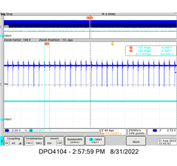
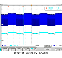
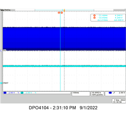
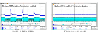
My customer has encountered a problem with bq25601. When the VBAT pin is under light load or no load, the buck charger should enter the PFM mode. However, the actual test waveform shows that bq25610 does not seem to enter the PFM mode under no load. Would you please confirm that this is normal? Can you explain the reason for this waveform?

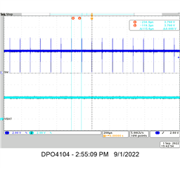
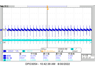
In OTG mode, When no-load, boost enters PFM mode. what made the different between buck mode and boost mode?

Thanks!

  • Hi Zhihao, 

    Can you provide your test condition for both buck and boost mode. 

    1. What is your VBUS, VBAT, and ICHG?
    2. Is the BAT pin floating? Or do you have an actual battery connected?   
    3. When you mentioned light load on BAT, is the load connected on BAT or SYS pin? 

    Regards, 

    Arelis G. Guerrero 

  • Hi Arelis,

    Thanks for you reply, the answer as below:

    1. What is your VBUS, VBAT, and ICHG?

    VBUS=5V, VBAT=4.2, ICHG=2.04A;

    2. Is the BAT pin floating? Or do you have an actual battery connected? 

    BAT connected with the electronic load; 

    3. When you mentioned light load on BAT, is the load connected on BAT or SYS pin?

    The load connected on BAT. 

    In fact, in the customer application, when the battery is full, the customer wants to turn off VBAT_CHG through the GAUGE, but the charger will continue charging at this time.

    Thanks!

  • Hi Zhihao,

    I replicated the test conditions you gave us in the lab. (VBUS = 5V, VBAT = 4.2V Stable, ICHC = 2.04A). Looking at the scope capture below, I am seeing correct PFM behavior on the SW test point when the battery is at 4.2V and the battery load current is very low (<20mA, 4.2V at BAT pin):

    Could you explain your waveform from the first two scope captures you shared? It looks like your battery is not at a stable 4.2V and is fluctuating. Even if you were to remove the battery, the BAT pins would still be regulated up to 4.2V so I would like to know why your VBAT appears to be either jumping to ~1V occasionally or stuck at 0V. Is there any offset in the VBAT measurement?

    Regards,

    James

  • Hi James,

    Thanks for your support.

    For the first scope, VBUS=5V, no load, termination enabled, the battery has been removed;

    For the second scope, VBUS=5V, no load, the battery also been removed, but termination was disabled;

    I don't think there is any offset in the VBAT measurement.

    Is there any possible that after the battery is removed, the charger continues to charge and discharge the BAT capacitor repeatedly, and lead to this result?

  • Hi Zhihao,

    It looks like you have a drain on your BAT voltage somewhere that is pulling the pins low. With no battery, the charge should be stored on a nearby capacitor.

    With no battery, charge termination enabled: Device continually tries to raise BAT pins to 4.2V for battery charging. After charge termination, the capacitor on BAT pins begins to discharge. ~250ms after charge termination, a new charging cycle begins and the process keeps repeating as BAT keeps falling below the recharge threshold. The SW node alternates between PWM and PFM as the charging current rises and falls. See the scope capture below.

    With no battery, charge termination disabled: Device raises BAT pins to 4.2V for battery charging. There is no charge termination so the buck tries to keep the BAT pins at 4.2V. The current needed to keep BAT capacitor at 4.2V is relatively low so the buck operates on the edge of PWM mode (almost in full PFM). See the scope capture below.

    For boost mode you should have a stable BAT voltage feeding the device. This is a scope capture I took at BAT = 3.7V (no load on VBUS).

    Regards,

    James

  • Hi James,

    Thanks for your support, that answered my question well!