This thread has been locked.

If you have a related question, please click the "Ask a related question" button in the top right corner. The newly created question will be automatically linked to this question.

BQ24600: RRC Battery not charging

Part Number: BQ24600

Hello,

I am using a BQ24600 to recharge a RRC Battery : RRC2054-2.

Here is the schematic :

Pins :

Pin Connected to
VBATIN Power Supply that might also be the battery itself
I_SET_CGE Digital Analog  Converter of a microcontroller
EN_CHARGE GPIO_OUTPUT of a microcontroller
CHARGE_STATUS GPIO_INPUT of a microcontroller
VBAT RRC Battery


Charger Configuration :

Vcc 24V
Icharge 1.74A
Vbat 16.4V
TS 1.9V

Battery Configuration :

VchargeMAX 16.8V
IchargeMAX 10A
Charge during tests 50%
I2C Connected

However, when I am setting ENABLE_CHARGE to '1', the battery is not charging.

ENABLE_CHARGE = '1' :

I_SET 360mV
PG/ 24mV
TS 1.9V
REGN 6V
VREF 3.3V
VCC 24V

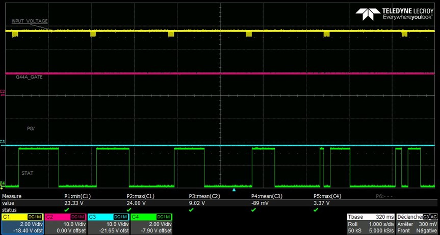
This is what I get on CHARGE_STATUS :

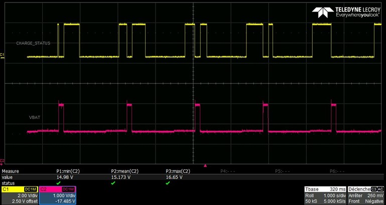
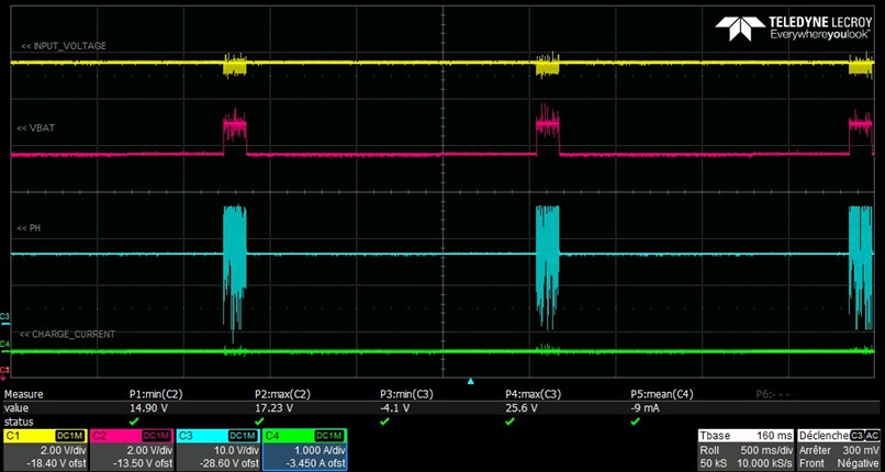
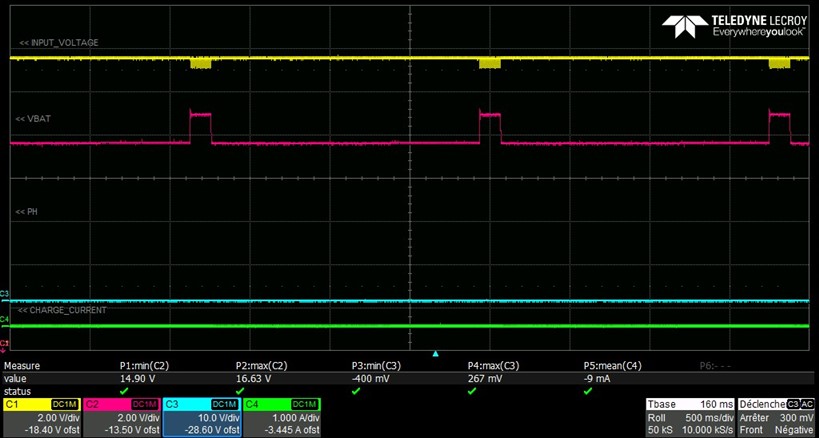
Yellow : CHARGE_STATUS
Red : VBAT

It is like my BQ24600 tries to recharge the battery, but then stop doing it.

Any help will be appreciated.
I can bring you more scopes if needed.

Regards,
Yan

  • Hello Yan,

    In order to assist with debug I need some more measurements.

    What is the value of VFB when this is happening?

    Can you please include a waveform of the input voltage, Q44A gate, PG, and STAT?

    In addition, can you please include a waveform of the input voltage, battery voltage, PH voltage, and charge current?

    Regards,

    Mike Emanuel

  • Hello Mike,

    Thanks for answering me.

    VFB = 2.1V

    On the bottom of each scope, you have measures done on each signal like min value, max value and mean value.

    Please find below the waveforms of the Input Voltage, Q44A Gate, PG/ and STAT :


    C1 - Yellow- : Input Voltage
    C2 - Red - : Q44A Gate
    C3 - Blue - : PG/
    C4 - Green- : STAT

    Please find below the waveforms of the Input Voltage, Battery Voltage, PH Voltage and Charge Current :

    C1 - Yellow- : Input Voltage
    C2 - Red - : VBAT
    C3 - Blue - : PH
    C4 - Green- : Charge Current

    As we can see, there is no current charge at all
    However, the blue signal is adding some noise on the others signals.

    On the following scope, I retired the blue signal :

    Finally, please find the scope of the PH Voltage zoomed In :


    Regards,

    Yan

  • Hi Yan,

    I have several things for you.

    1. If VFB is 2.1 V, charge is complete. The regulation voltage for the VFB pin is 2.1 V. Have you double checked your regulation point? What is your applied battery voltage and what is your designed charge voltage regulation? You state that max voltage is 16.4 V setting, but one waveform shows a max of 17.23 V.

    2. The STAT pin only blinks at 0.5 Hz for "charge suspend, timer fault, input overvoltage, battery absent." Charge suspend relates to the TS pin. Has your charge timer expired? I do not see you exceeding 28 V on the input. You confirmed you have a battery attached?

    3. The input signal looks clean, always connected.

    Regards,

    Mike Emanuel

  • Hi Mike,

    1. For the battery voltage, refer to the Figure 3 because I have some noise on the Figure 2. As you can see, VbatMAX = 16.63V because of the little spike when the voltage is rising. When stable, Vbat = 16.41V.
    However, the optimal recharge voltage for the RRC battery is 16.8V. So I tried others couples of resistors to be around 16.8V, but it did not solve my problem.
    I am waiting for +/-0.1% resistors to resume my tests.

    2. I confirm I have a battery attached. Otherwise I would have 0V on Vbat when the BQ24600 is not trying to recharge the battery -see Figure 2 and 3-. What is the charge timer?

    Regards,

    Yan

  • Hi Yan,

    Looking at your schematic, your maximum voltage regulation of the battery is 16.4 V and your recharge voltage is 16.0 V. If you are applying at or over 16.4 V you are on the edge of CV mode or just in over-voltage of the battery. Please confirm the FB resistors of the charger. For the timer, check out the "Safety Timer" in the Electrical Characteristics Table. 

    Regards,

    Mike Emanuel

  • Hello Mike,

    As I said in my first message, VchargeMAX = 16.8V.
    According the RRC battery datasheet, the over-voltage protection is activated when Vcharge = 17.08V when temperature is between 10 and 50°C.

    I confirm R202 = 150kΩ and R204 = 22kΩ.

    I also checked the charge timer : every time I am testing the BQ24600, I just let the battery connected for a few minutes, so the charge timer had not expired.

    I guess the problem comes from the RRC battery.
    I will contact you if I find something new.

    Regards,
    Yan

  • Hi Yan,

    Keep me posted.

    Regards,

    Mike Emanuel

  • Hi Mike,

    I solved my problem.
    In fact, there were 2 problems :

    • pull-up resistors value of the SMBus of the battery was not correct : previous value 3.3kΩ, new value 10kΩ.
    • between the battery and the charger we have a MOSFET in parallel with a diode : the diode let the current goes from the battery to the charger, that is why I had the battery voltage on the SRN pin of the BQ24600. However, the transistor should be commanded to short-circuit the diode to let the current pass from the charger to the battery. The pin configuration of my microcontroller was not correct, therefore the transistor remained cut off.
      I fixed it, and now everything is working perfectly.

    Thanks for helping me.

    Regards,

    Yan